Diamonite Electrathon America Racer

Functional Artist

Well-known member
Messages
5,587
Reaction score
3,188
Location
Toledo, Ohio
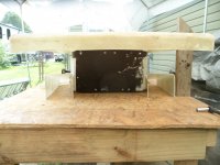
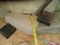
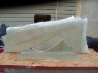
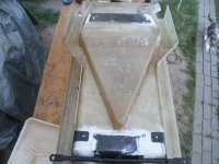
Should "go" about here
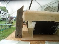
...checkin' the "fit"
SAM_8613 (1).JPG
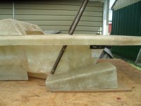
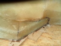
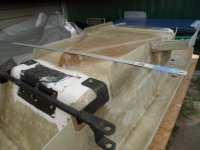
The "opening" seems ta "line up"
...about where we need it ta be :thumbsup:
SAM_8615 (1).JPG
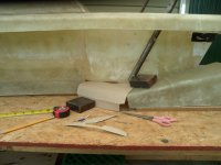
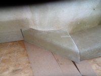
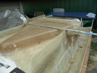
Seems like we need ta do a bit more trimmin'
SAM_8614 (1).JPG
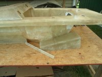
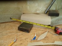
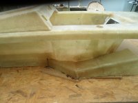
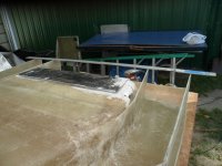
Back to/on the mold
...& took ~1" off of the bottom edges ;)
SAM_8616 (1).JPG
 

Functional Artist

Well-known member
Messages
5,587
Reaction score
3,188
Location
Toledo, Ohio
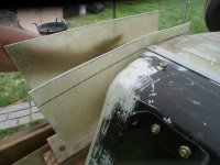
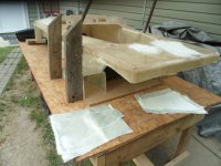
After makin' sure of the "fit" of the first "tunnel"
...I did some adjustin' on the "cut out lines"
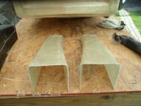
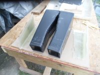
...then, went ahead & cut out the second "tunnel"
SAM_8626 (1).JPG
...& then, there were (2) ;)
* Custom shaped ta "hug" the sides of the monocoque
SAM_8628 (1).JPG
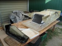
Flipper 'er over (right side up)
...double checked the "fit"
...& worked on/thinkin' about how ta do, the connectin' duct work :unsure:
SAM_8631 (1).JPG
...& then, there were (2)
...AKA "Duals" :2guns:
SAM_8634 (1).JPG
 

Functional Artist

Well-known member
Messages
5,587
Reaction score
3,188
Location
Toledo, Ohio
Made sure the front roll bar still mounts properly
...& "clears" the "tunnel"

Yup, looks good! :thumbsup:
SAM_8637 (1).JPG
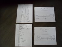
CAD duct work
SAM_8639 (1).JPG
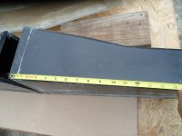
Looks like the "piece(s)" we would need are ~10" - 12" long
SAM_8641 (1).JPG
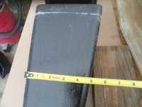
...& ~4 1/2" at the widest part
SAM_8642 (1).JPG
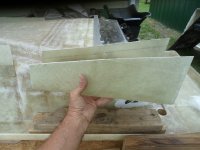
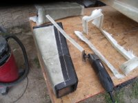
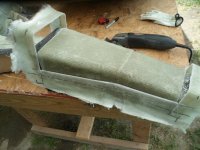
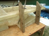
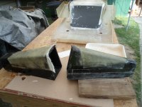
I'ma thinkin' that the "tunnel" molds may be useful for makin' these "pieces"

Yup, looks like we can get a ~10" - 12" piece off of it
SAM_8644 (1).JPG
Even the narrowest part of the mold is ~4 1/2"
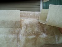
...& there are still already coated with PVA

So, yea! I ain't gotta make more molds :wai:
SAM_8645 (1).JPG
 

Functional Artist

Well-known member
Messages
5,587
Reaction score
3,188
Location
Toledo, Ohio
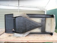
An (inverted) view of the "air channels"
SAM_8687 (1).JPG
Since we added all of this stuff "hangin' down"
...let's make sure everything is nice-n-even with the bottom of the racer :thumbsup:

Air Intake area
SAM_8690 (1).JPG
Throat area
SAM_8691 (1).JPG
The Tunnels
SAM_8694 (1).JPG
Flipped 'er back over

* Notice the "nose" is ~1" higher than the actual floor of the racer
...for even better unobstructed air flow
...into the under car aero system
SAM_8699 (1).JPG
 

Functional Artist

Well-known member
Messages
5,587
Reaction score
3,188
Location
Toledo, Ohio
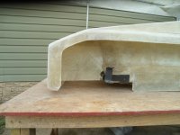
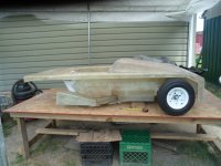
I put the front wheels on & leveler 'er out
...ta check on ground clearance
SAM_8677 (1).JPG
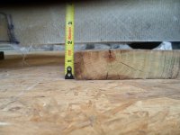
Looks like the bottom will "ride" just under 2" off of the ground
SAM_8679 (1).JPG
On ground clearance, the EA rule book states:
10 WHEELS and TIRES
1. Tires must be a pneumatic (inflatable) type.
2. Wheels and tires of any diameter or width may be used.
3. The minimum ground clearance is to be judged by the cars ability to roll over a 2x2 that is milled to be1½”x1½”.
This is to prevent the vehicle from sliding on the ground in the event of failure of any or all of the tires. (page 8.)

So, we look ta be "in compliance" :thumbsup:

Here is a view of the front ground clearance
...with the wheels on ;)
SAM_8683 (1).JPG
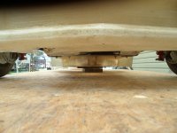
A view of the air intake area
...from up/underneath
...as it will "ride down the road" :cheers2:
SAM_8684 (1).JPG
 

Functional Artist

Well-known member
Messages
5,587
Reaction score
3,188
Location
Toledo, Ohio
The venturi principle described above is exclusive to a closed system, or pipe. Half of this "pipe" is open to the atmosphere, so different rules apply.
Hey Ez,
I've been thinkin' about your comment, a bit more
...&/so, have some "jabberin' ta do" :thumbsup:

Because "part" (not half, due to the roadway) of the "pipe" is "open to the atmosphere"
...I guess this situation could be referred to as a "leaky pipe" :confused:

I thought (durin' a 'bout of free thought) about the possibility of enclosing part, if not all of the air channels
...to help alleviate this "leakyness"

But/then, thought
...if any effect (like creating a low pressure area) was to occur
...it would occur inside of the enclosed pipe
&
Would NOT create a pressure difference
...between the air pressure above the racer
...& the air pressure below it :(

Also/then, thought about how most times when describing air flow
...most folks refer to the air as having "layers"

So, (again, while in free thought) I was thinkin' that with ~2" of ground clearance
...& an additional ~1" under the front bumper
...basically, there is ~3" of unobstructed air flowing under, the front of the racer :auto:

So/now, let's say each of them (3) "layers" are 1" thick or tall
&
When, them (3) ~1" "layers" of air flow under the front of the racer
...the bottom "layer" still just flows along, mostly unobstructed
...but, them (2) upper "layers" of air encounter the undercar aero feature
&
Get "funneled" into the air Intake
...compressed in the Throat
...& then, expands as it exits out thru the Tunnels :2guns:

So/maybe the lower "layer" of air "acts" as an "air curtain"
...to help "seal" the "leaky pipe" :cheers2:
 
Last edited:

Functional Artist

Well-known member
Messages
5,587
Reaction score
3,188
Location
Toledo, Ohio
If anyone is really interested in undercar aero
...& wants to understand why I'ma doin' all of this :unsure:
...this video explains a lot of it pretty well :thumbsup:

The video is about aerodynamic affects (& testing) on a really mini-racer (an RC car)
...but, the concepts are the same ;)

* The good info starts about 3:00 into the video :cheers2:
 

Functional Artist

Well-known member
Messages
5,587
Reaction score
3,188
Location
Toledo, Ohio
Too much? :unsure:
Too deep?? :geek:
Too soon??? :ROFLMAO:

I mainly wanted to "make a note" of some of
...what I wasa thinkin'
...& why I wasa doin' what I'ma doin' :cheers2:
But/also,
To share with "the world"
..."how we got to where we are" with this project
...as "this sh*t doesn't "just happen" :thumbsup:

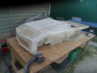
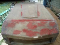
Movin' on to actual "body work"
SAM_8717 (1).JPG
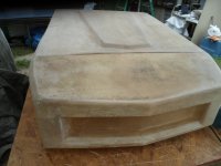
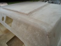
Lots of sandin'
SAM_8720 (1).JPG
Yup here too
SAM_8721 (1).JPG
 

Functional Artist

Well-known member
Messages
5,587
Reaction score
3,188
Location
Toledo, Ohio
My arms don't like me sanding
...so, "we" made a "deal" that I would only sand for ~20 minutes at a time
&/so,
This gave me "time" to work on some other projects (in between)

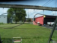
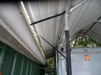
Like, there is a big 'ol "gap" in between my work area/shelter & the garage
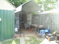
* Wow! check out this "old pic" I found of my work area, from a coupla years ago :smiley_omg:
SAM_8711.JPG
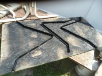
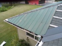
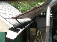
I've been thinkin' that I could make a couplea simple brackets, to kinda "extend" the side a bit

So, this way, any rain will "run" off the shelter & "right" into the gutter, on the garage ;)
Like these:
SAM_8709 (1).JPG
I also, cleaned up & painted the roll bars, while I wasa at it, too :cheers2:
SAM_8710 (1).JPG
 

Functional Artist

Well-known member
Messages
5,587
Reaction score
3,188
Location
Toledo, Ohio
The venturi principle described above is exclusive to a closed system, or pipe. Half of this "pipe" is open to the atmosphere, so different rules apply.
Hey Ez,

Sorry, I'ma not tryin' ta "hound" ya about this :innocent:
...but, still thinkin' about "if" a "closed system" is absolutely required, for the Venturi effect to occur :unsure:
&
Wasa thinkin' that the "wind funnels between tall buildings" example, used in the description
1.) is not in a closed system
2.) high wind speed does not seem to be required, for the effect to occur

The Venturi effect is a phenomenon where a fluid’s speed increases as it travels through a constricted section of a pipe. This increase in velocity results in a simultaneous decrease in the fluid’s static pressure. The principle is observable in various natural and man-made environments, from the way wind funnels between tall buildings to its use in complex machinery.
&
The mechanics of the Venturi effect are illustrated using a Venturi tube, which has a wide entrance that narrows into a constricted throat before widening again. To maintain a constant flow rate as fluid passes through the smaller throat, its velocity must increase.

This relationship between velocity and pressure is explained by the Bernoulli principle. The principle states that for a fluid in motion, an increase in speed occurs alongside a decrease in pressure. In the Venturi tube, the highest fluid velocity and lowest pressure are therefore reached within the throat.

This can be visualized as a crowd moving down a hallway that narrows to a single doorway. Each person must speed up to pass through the constrained opening. Similarly, fluid particles accelerate through the throat, causing a drop in pressure. After the throat, the tube widens, allowing the fluid to slow and its pressure to increase toward its initial level.

&/also,
Think of a leaf floatin' down a stream
...& when "it" encounters a narrowed section, of the stream "it" speeds up
...while "passing thru" the narrowed area (throat)

Same with a Kayaker in a river
...just on a bigger scale

All (3) of these examples (people, leaf, kayaker)
...are not in closed systems
...& high speed does not seem to be required, for the effect to occur...either :thumbsup:
 

Functional Artist

Well-known member
Messages
5,587
Reaction score
3,188
Location
Toledo, Ohio
While the paint wasa dryin', I did another (rep) 20 min of sandin'
...& then, went up on the roof ta access the damage

I've been "puttin' it off" 'cause of 90+* temps
...then, the smoke
&
I've also, been kinda of obsessed with this EA racer :innocent::devil2:

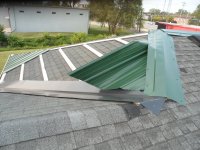
This is what I found :eek:

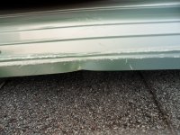
This panel is "trash"
...& that piece of cap is too :(
SAM_8740 (1).JPG
The smaller panel, further away in the pic, seems to have gotten damaged too
SAM_8741 (1).JPG
It's not all of that bad
...the edge got a little bit bent
...& some scuffs & scratches
But,
My father always told me "if your gonna do something...do it right" :cheers2:

So, yea, it's gotta go :thumbsup:
SAM_8743 (1).JPG
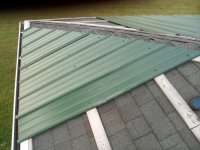
Panel replaced
* Theys a bit dirty from storage
...but, I'ma countin' on the next rainstorm ta "wash 'em off" for me ;)
SAM_8744 (1).JPG
 

ezcome-ezgo

G'me sumthin to write on
Messages
5,961
Reaction score
2,949
Location
Atlanta, GA
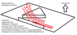
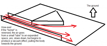
FA, the venturi principle you describe is 100%, and I am not trying to debate it. What I am suggesting is perhaps best illustrated: If you take a funnel (which is not unlike the underside of your delightful project here) and you pour - say - oil into it. But you pour it too fast and what happens? It overflows. The air rushing into your under-vehicle funnel will follow the path of least resistance, which is not rushing through a narrow opening. I am not a scientist, so the explanation of my point is being made poorly.
1785417673027.png
1785418212128.png
 

Functional Artist

Well-known member
Messages
5,587
Reaction score
3,188
Location
Toledo, Ohio
Hey Ez,

I really appreciate ya helpin' ta expand on this discussion
...for me & for everyone else too :thumbsup:
&
I think we are mostly "on the same page" :cheers2:
&/so
I gots some more jabberin'

Your first illustration
I agree, the Intake can't be too big, as compared to the Throat (or bottleneck) (kinda like what the jet does in a carb) :)
...or (as you describe) the (funnel) will overflow (or the engine will run too "rich"&/or "flood" the engine with fuel) :confused:

Your second illustration, seems to be describing the effect (I'm hopin' ta get from) of the Expansion Tunnels :2guns:

I did some drawin' too
SAM_8860 (1).JPG
Some folks might not realize that
1.) the bottom of the racer is (2) separate (left & right) Venturi Tunnels
2.) the Intake is 2D (2 dimensional) (~2" tall throughout)
...while the Expansion Tunnels are 3D (3 dimensional) (going from ~4"t at the front thru ~10" at the rear) ;)

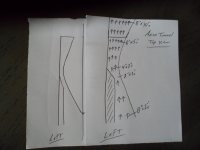
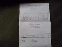
I drew up an illustration of the left Air Channel

Notice the "channel" is ~8"w x ~2"t at its Intake
...then, narrows to ~2"w x ~2"t at its Throat
&
Then, it starts to expand to ~4"w x ~2"t at the opening of the "base" Tunnel
...& continually expands to ~6"w x ~5"t at the end of this "base" (or intermediate section) of the Tunnel

If/when, we add the Tunnel extensions
...the Tunnels will then, continually expand from ~6"w x ~5"t
...up to ~8"w x ~10"t
...while exiting out the rear of the racer

Top view
SAM_8861 (1).JPG
Side view
* Also, the front of the racer is ~3" off the ground
...the top of the Air Channels are ~4" off of the ground

So, there is ~1" of available expansion area, before the flowing air gets to the Throat
...& then, the expansion level "explodes" after the air flow "gets thru" the Throat
SAM_8862 (1).JPG
* So, the "trick" is to figure out the proper "metering" (Intake vs. Throat vs. Exhaust Tunnels)
...so, we don't "overflow" the funnel :cheers2:

Also, most Venturi Tunnel are illustrated as symmetrical
...but, I'ma thinkin'/it seem like an asymmetrical system may actually "work better"

Because "if" the Intake is smaller than the exit
or
Having a larger exhaust, than intake
...may help or enhance the "suction" effect :wai:
SAM_8863 (1).JPG
 

Functional Artist
Well-known member
Messages
5,587
Reaction score
3,188
Location
Toledo, Ohio
the "trick" is to figure out the proper "metering" (Intake vs. Throat vs. Exhaust Tunnels)
...so, we don't "overflow" the funnel
I should have included "volumes" :innocent::devil2:

The "Air Channel" is ~8"w x ~2"t at its Intake (~16 sq. in.) of volume
...then, narrows to ~2"w x ~2"t at its Throat (~4sq. in.)
&
Then, it starts to expand to ~4"w x ~2"t (~8 sq. in.) at the opening of the "base" Tunnel
...& continually expands to ~6"w x ~5"t (~30 sq. in.) at the end of this "base" (or intermediate section) of the Tunnel

If/when, we add the Tunnel extensions
...the Tunnels will then, continually expand from ~6"w x ~5"t (~30 sq. in.)
...up to ~8"w x ~10"t (~80 sq. in.) of volume
...while exiting out the rear of the racer


So, currently "we" have ~16 sq. in. of volume, coming in thru the Intake
...that will be "compressed" down to ~4 sq. in. at the Throat (a ~4:1 reduction)

Then, that ~4 sq. in. of volume starts to increase to ~8 sq. in. at the beginning of the tunnel (a ~2:1 increase)
&
Then, it continues to increase to ~30 sq. in. of volume, at the exit, of the Tunnel (a ~3.75:1 increase)
&
Then, "if" we add the Tunnel extensions
...the volume will increase from ~30 sq. in. up to ~80 sq. in.
...
that is going out of the Exhaust Tunnels (a ~2.5:1 expansion)

So/basically, we have
...~16 sq. in. reducing down to ~4 sq. in.
...for a ~4:1 reduction ratio
&
Then, from ~4 sq. in. increasing up to ~80 sq. in
...for a ~20:1 expansion ratio :2guns:
 

Functional Artist

Well-known member
Messages
5,587
Reaction score
3,188
Location
Toledo, Ohio
I think (I hope) I'ma about done sandin'
...top, bottom, sides, nooks-n-crannies...everything

So, after some clean up (dust management & removal)
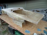
...I "blackened" the under workin's ;)

Really "highlights" them Air Channels :2guns:
SAM_8749 (1).JPG
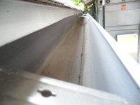
Whilst the paint dried, I cleaned out the gutters on the garage
SAM_8736 (1).JPG
All spic-n-span
SAM_8737 (1).JPG
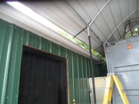
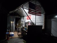
Also, added a light to my shelter/work area
SAM_8746 (1).JPG
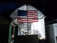
Another view USA...USA...USA :wai:
SAM_8747 (1).JPG
 
Top