Diamonite Electrathon America Racer

Functional Artist

Well-known member
Messages
5,530
Reaction score
3,116
Location
Toledo, Ohio
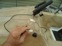
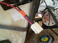
I added a connector to the Brake Lever/Brake light switch connection
...will be hidden behind the dash

This is so, the Lever is removable from the wiring harness
...& NOT permanently "hard wired" to it ;)
SAM_8361 (1).JPG
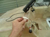
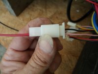
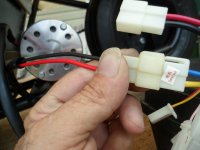
Again, just Plug-n-Play
* Notice, the wire colors are connected (same/same) :thumbsup:
SAM_8362 (1).JPG
 

Functional Artist

Well-known member
Messages
5,530
Reaction score
3,116
Location
Toledo, Ohio
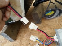
Power wires (AKA Battery Cables)
The Positive (+) & Negative (-) power wire connector, at the Speed Controller
SAM_8347 (1).JPG
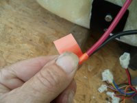
I used some Orange Vinyl tape to "bundle" the power wires together

* Taping tip: try-n-not touch the end of the tape when installing
...as to NOT contaminate or reduce the "stickability" of the "end" of the tape :thumbsup:
SAM_8348 (1).JPG
On most EV's Orange "wrapping" indicates that they are the "High(er) Voltage" power wires
SAM_8349 (1).JPG
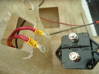
The Positive "battery cable" goes from the SC to the Circuit Breaker, first (Load)
...then, goes to the Battery pack (Batt)

* I labeled 'em for future reference :cheers2:
SAM_8364 (1).JPG
 

Functional Artist

Well-known member
Messages
5,530
Reaction score
3,116
Location
Toledo, Ohio
Let's discuss Speed Controllers

For this racer, we need a speed controller for a 48V system
...& 1,000W brushed motor

Here is the Yalu Model YL-03 48V 1,000W speed controller
...that came with the motor kit
...but, the label (on it) doesn't have much info
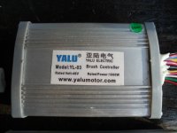
SAM_8240 (1).JPG
To help explain further
...this WYYS48 is a 48V 1,000W SC (speed controller)
...that I "fried" a whilst back :eek:
...but, the label, on this one, has more info :thumbsup:

Model #: WYYS48
Power: 1,000W (for up to 1,000W motor)
Voltage: 48VDC (for use with 48V systems/battery packs)
Current: 32A (nominal current capacity 32 Amps)
Short Voltage: 42V (controller will "shut off" when the 48V battery pack, gets below ~42V)
Throttle Voltage: 1-4V (controller accepts throttles with a 1V-4V range)
Function: Reverse: (controller has additional Reverse feature)
Production Date: 20220910 (Made on Sept. 10, 2022)
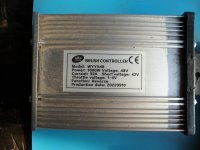
SAM_8242 (1).JPG
Here is the wiring diagram that came with the kit
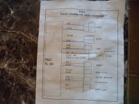
SAM_8387 (1).JPG
These are the big Power Wires
...Red (+) Black (-) are the Battery cables
...& Yellow & Blue are the Motors Power cables
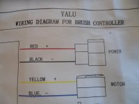
SAM_8388 (1).JPG
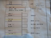
These are the smaller Signal wires
...like Power Lock (On/Off), Throttle, Charger (Battery Charger connection), Brake (switch), Voltage Meter & Brake light(s) :geek:
SAM_8389 (1).JPG
Also/supplemental, Warning & Instructions
SAM_8390 (1).JPG
 

Functional Artist

Well-known member
Messages
5,530
Reaction score
3,116
Location
Toledo, Ohio
Now, let's discuss the Power Meter (required in the EA handbook)

INSTRUMENTS
The goal of Electrathon is to see how far you can go in an hour. To do that effectively, you will need to know what you vehicle is doing, so instrumentation is essential. Amperage and voltage are the most important things to know. Simple analog gauges will work, but it's hard to see the needle and small numbers when you and they are bouncing around in a race. Digital units (E-Meters) are more expensive, but they are much more precise, easier to read, and will record the data over time, so at the end of a race you can tell the total number of amp or watt hours you've used. Either way, your meter needs to be connected to a shunt, which is a chunk of metal of known resistance that current flows thru.
(page 24.)

I'm using a PZEM-051 power meter

These are the specs on the box :geek:

Type: for DC systems (check)
Model: 051 (check)
Parts: Includes a 100A Shunt (check)

Made in China: ya...ya...whatever :devil2:...for now :innocent:
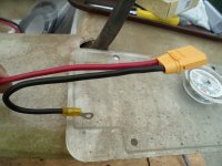
SAM_8368 (1).JPG
In the manual there are:

Specification parameters:
1. Working Voltage: 6.5VDC - 100VDC
2. Test voltage: 6.5VDC - 100VDC
3. Rated Power: 100A/1,000W
4. Measurement accuracy: 1.0 grade


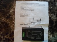
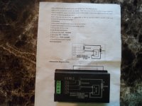
Has a wiring diagram printed in the manual
...&/also, right on the back of the meter too ;)
SAM_8395 (1).JPG
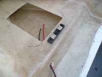
I'ma thinkin' ta probably mount the Shunt
...up/under here
...right next to the battery :thumbsup:
SAM_8373 (1).JPG
 

Functional Artist

Well-known member
Messages
5,530
Reaction score
3,116
Location
Toledo, Ohio
Ju-alla says "Hey that doesn't look like a 100A Shunt"

I'ma says "good eye" :thumbsup:

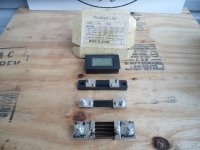
On top is a PZEM-051 power meter
#2: is a 50A Shunt
#3 is a 100A Shunt
#4 is a 500A Shunt
SAM_8367 (1).JPG
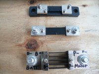
Well, it seems that Shunts are calibrated by size

The 50A unit is for systems up to ~50A
The 100A unit is for systems up to ~100A
The 500A unit is for systems up to ~500A

* Hence the difference in sizes
...& the difference in the battery cable connection (bolt) sizes too
SAM_8369 (1).JPG
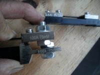
They are basically interchangeable (as long as the measurement specs are the same)

Yup, all (3) versions are labeled (75mV)
SAM_8370 (1).JPG
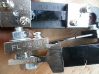
All (3) versions are also labeled (FL-2 0.5)
SAM_8372 (1).JPG
Since the system, in this racer is under 50A, I figured a 50A Shunt wasa the "better choice"

* Also, from past experience(s), using a Shunt with closely matching specs, seems to produce a bit more accurate info/data :2guns:

So, Ju-alla, that'sa why we B usin' a 50A Shunt :cheers2:
 

Functional Artist

Well-known member
Messages
5,530
Reaction score
3,116
Location
Toledo, Ohio
What is a Shunt?

Technically:
A shunt is a device designed to provide a low-impedance path for an electrical current in a circuit. Electrical shunts are used in a wide variety of applications including power distribution systems, electrical measurement systems, automotive and marine applications. In current measurement, a shunt is a resistor of very low but precisely known resistance placed in parallel with a meter, allowing large currents to be measured indirectly via the voltage drop across it.

Basically:
A simple metal component
...wired "in line" with the Negative (-) Battery cable
...with "sense wires" on each side
...that sends info/data to a meter
...which then, displays the info "in real time" on its screen

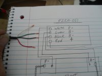
Again, here is the wiring diagram (in the manual & on the meter)
...that I went off of
SAM_8395 (1).JPG
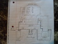
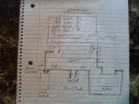
I did a drawin' of my own
...on how ta connect 'er :thumbsup:
SAM_8398 (1).JPG
Also, I want to try-n-keep the wiring of these power meters
...on ALL of my racers consistent

* For easy inter-changeability of parts amoungst different racers
&
Ta help keep 'em "idiot proof"
...by ALWAYS having them wired "basically" the same :sifone:

So, ta "double check" on the wire colors
...that I used on previously ta wire up my PZEM-051 power meters
...I went back to the build thread for my Sequoia EA racer (~post #430)
https://www.diygokarts.com/community/threads/sequoia-electrathon-racer.48137/
...& found these pics

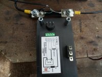
Backside of the meter
...& Shunt
SAM_2352 (1).JPG
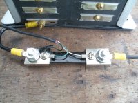
Upper closer view of the Shunt wireing
SAM_2351 (1).JPG
 

Functional Artist

Well-known member
Messages
5,530
Reaction score
3,116
Location
Toledo, Ohio
Ok, now that we have the wiring "info"
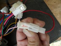
...we can work on gettin' the Shunt "wired up"

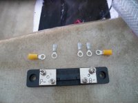
I rounded up some wiring "hardware" (terminals)
...the Yellow ones, for the Battery "cables"
...& the Blue ones, for the signal wires
SAM_8376 (1).JPG
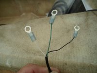
Stripped the ends of the wires
...& doubled 'em up
SAM_8379 (1).JPG
Signal terminals, installed
SAM_8380 (1).JPG
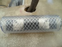
Since the Shunt is "basically" a "part of" the Negative battery cable
...I'm gonnsa insulate it (add an insulating cover)

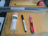
*This 1 3/8" OD Vinyl tube does a pretty good "job"

** Notice I used a straight edge ta "mark a line"?
SAM_8381 (1).JPG
Split 'er right down the middle
SAM_8383 (1).JPG
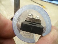
Shunt slides "right in"
...& the wires & cables will just "run" out of the ends
SAM_8384 (1).JPG
Side view
SAM_8385 (1).JPG
 

Functional Artist

Well-known member
Messages
5,530
Reaction score
3,116
Location
Toledo, Ohio
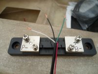
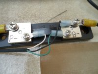
Here is the Shunt, all wired up
SAM_8403 (1).JPG
As per the diagram
White wire goes to the P- "signal wire" connecting bolt, on the Shunt
...the Green wire goes to the B- "signal wire" connecting bolt, on the Shunt
...& the Black wire goes to the B- "battery cable" connecting bolt, on the Shunt

* The Red Positive (+) wire & the Black Negative (-) wires "power" the meter
...& the White & Green wires, are the "signal" wires

** The Red Positive (+) wire
...doesn't "go" to the Shunt
...because that "is" the Negative (-) Battery cable

The Red wire can "go" to the positive (+) Battery terminal
...but, the meter will be "on" all of the time
or
The Red wire can "go" to the "Load" side of the Circuit Breaker
...& the meter will only be "on" when the system is powered
or
The Red wire can be connected to the "Indicator/meter" connecting plug, on the SC
...& the meter will only come on when the SC is "switched on"

I like #3 because, when the meter is "on", I know the SC is "on" & the racer is "ready to go" :auto:
SAM_8398 (1).JPG
Shunt all wired up"
...with "protective cover"
SAM_8404 (1).JPG
 

Functional Artist

Well-known member
Messages
5,530
Reaction score
3,116
Location
Toledo, Ohio
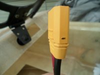
Hey that is a pretty kool lookin' connector, ya got
...ta connect your harness, to the battery pack

What is it? :unsure:

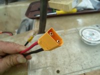
Well, that there, my friend, is a XT90 connector :cool:
SAM_8400 (1).JPG
They are a bit more HD than the White Molex type connectors
...& for better "contact" & longevity, the terminals are even gold plated :wai:
&
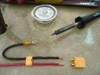
They have ta be soldered on to the wires/cables

All ready for the procedure
SAM_8399 (1).JPG
After installation, they look like this :thumbsup:
SAM_8401 (1).JPG
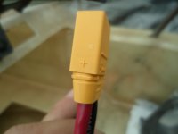
* Notice, because of the way they are shaped
...they can only be "plugged in" (1) way
&
They even have the "polarity" marked right on them ;)

Positive (+) side
SAM_8406 (1).JPG
Negative (-) side
SAM_8407 (1).JPG
 

Functional Artist

Well-known member
Messages
5,530
Reaction score
3,116
Location
Toledo, Ohio
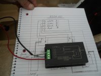
Now, let's get the "brains" & "display" of the PZEM-051 connected

Double checkin'
...& alignin' the wire colors, with the diagram :thumbsup:
SAM_8413 (1).JPG
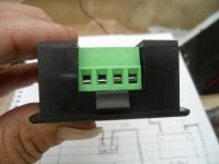
The wires connect to the meter by/with these little "gates"

Just untighten the screw & the "gate" drops down/opens
* The (2) "gates" on the left side are "opened"
...& the other (2) gates are closed
SAM_8414 (1).JPG
Got 'er all connected up, as per the diagram :geek:
SAM_8419 (1).JPG
The Red "power" wire gets connected to, the pink wire of the "Indicator" plug, on the SC
SAM_8416 (1).JPG
** The Negative (-) wire, of this plug, is not needed
...because the Negative (-) wire is connected directly to the Shunt (AKA part of the Negative (-) battery cable) ;)
SAM_8418 (1).JPG
 
Top