buggy go kart thing with overpriced cm250 engine

Status
Not open for further replies.

fowler

New member
Messages
5,463
Reaction score
16
Location
Bullsbrook West Aus
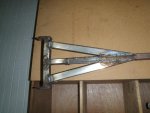
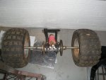
i finished the back swing arm mounts then i added some supports
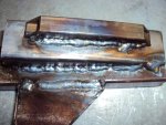
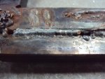
i tryed the straight line welding and f***ed it so i did the overlapping circles that went well
got so pics just waiting for the pics to be mailed from a mates camera
 

fowler

New member
Messages
5,463
Reaction score
16
Location
Bullsbrook West Aus
welding is still not as good as it needs to be
the top is straight line weld and the bottom is the standard zig zag
the other pic is the rear swing arm
im just going to spend the next day or so getting the circles right then mount the engine
 

Attachments

  • buggy 2.jpg
    buggy 2.jpg
    66.8 KB · Views: 53
  • buggy 3.jpg
    buggy 3.jpg
    83.1 KB · Views: 49

brendonv

New member
Messages
861
Reaction score
3
Location
Australia, Perth
The welding reminds me of my first welds on my kart. Look horrible and im unsure at how they hold but ive had 100kg+ people on my kart and it hasnt broken for the 2 years ive had it.
 

fowler

New member
Messages
5,463
Reaction score
16
Location
Bullsbrook West Aus
did some pracice on some scrape metal
jagged one ultimate weld then i couldnt replicate it
they were alright though got pics to out up soon
 

Cam

Nz Petrolhead
Messages
487
Reaction score
2
Location
Whangarei, New Zealand
Try when your practicing on some 6mm+ scrap plate, it absorbs the heat better and its easier to practice on

Just keep that little molten pool behind the wire, and your hand movements consistant,

Sometimes the tip is resting on the steel and as your going along it stutters and jumps.

Like how the project is going.

Cheers, Cam.
 

fowler

New member
Messages
5,463
Reaction score
16
Location
Bullsbrook West Aus
better?
what am i looking for
what is better
what can i improve on the better one

thankyou
 

Attachments

  • better.jpg
    better.jpg
    49 KB · Views: 39
  • DSC00759_JPG.jpg
    DSC00759_JPG.jpg
    42.9 KB · Views: 37

r97

Measure twice cut once
Messages
3,793
Reaction score
8
Location
Massachusetts, USA
first pic going from top to bottom, first weld looks okay (circles! or triangles or whatever method you prefer) most importantly it has a heat signutare, second bead doesnt look great and no heat signurature, bottom one has a great bead butno heat signature, so it looks nice but breaks easly. the second pic has a nice bead and what looks like a heat signature but the metal is spaced too far apart. this is just my opinoin, dont rely on me to judge your welds strength have someone look at them in person, and test them with mr vise clamp and uncle sledge hammer, good luck
 

fowler

New member
Messages
5,463
Reaction score
16
Location
Bullsbrook West Aus
non of the teachers at school can realy weld (they taught me the ziz zaz)
but i did bash the crap outa it with a malet to no result
 

redsox985

Active member
Messages
4,092
Reaction score
11
Location
PA
Hahaha. Ok the first picture. I like the bottom weld the most, the bead looks good but it looks like it's sitting on the metal. The second picture has a good bead and maybe even too much penetration. Do you see how it looks like it ate away at the edge of the metal? That's my only concern.
 

r97

Measure twice cut once
Messages
3,793
Reaction score
8
Location
Massachusetts, USA
sry, im saying try welding flat bar together and whacking it with a sledge hammer because its more of a test of your weld. and redsox, if you ask me nothing penetraits too much unless it burns through
 

fowler

New member
Messages
5,463
Reaction score
16
Location
Bullsbrook West Aus
nealy finished making the sprocket hub
sorry for the deathly slow pace if anyone is acctually following this build
i only get 45 mins day and only 4 days in the week
 

fowler

New member
Messages
5,463
Reaction score
16
Location
Bullsbrook West Aus
ok this is my reson for makeing the sprocket hub
when picked up the engine me and a mate worked out the drive chain that came from the quad bike and matches the rear sprocket shoud fit on the drive sharft

but when i was able to get the engine to the DT centre and remove the flywheel caseing and replace the drive sprocket it became evident i was badly mistaken and it isnt close to fiting

the only options were to either buy a new drive sprocket or make the free rear sprocket that came free with the engine
fit on the axil
so i chose the cheap option and i had to make a conversion to make it fit
this is the result so far
the first pic shows the gold sprocket that came off and the silver onre is going on
the second pic is the two drive sprockets (it is evident how wrong i was
the third pic is the convertion ( a 1cm barby plate that i remodeled)
EDIT
wait what are securaty tokens it wont let me upload pics
 

fowler

New member
Messages
5,463
Reaction score
16
Location
Bullsbrook West Aus
o turns out i need every thing in paint and re save it
even though it was already jpeg
 

Attachments

  • 1.jpg
    1.jpg
    87.7 KB · Views: 13
  • 2.jpg
    2.jpg
    117 KB · Views: 15
  • 3.jpg
    3.jpg
    94.6 KB · Views: 17
Status
Not open for further replies.
Top