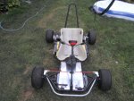
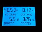
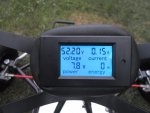
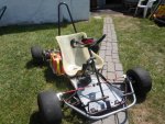
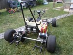
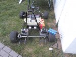
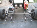
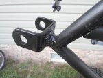
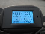
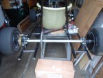
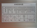
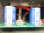
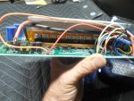
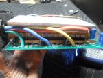
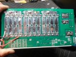
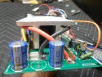
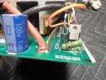
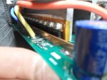
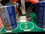
The wiring definition, for this controller, does not show, list or require a contactor or a precharge circuit.
...so, I was wondering "if" they may be incorporated into the controller.
(these components are usually required on "bigger"/ higher voltage controllers like this)
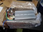
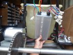
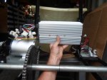
But, I would have to say, NO there is NOT any type of contactor, inside of the controller
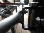
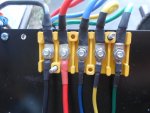
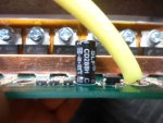
...because when we looked inside of the controller, we could see that the power cables (that connect to the batt pack) are directly connected to the "rails".
...& if there is not a contactor (switch) in there then, there can NOT be a precharge circuit either.
Why would there be a need for a contactor

...&/or a precharge circuit if the wiring definition (from the factory) does not show or require them?
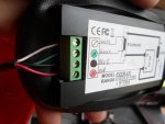
Well first, a contactor is basically a big beefy electronic switch/relay.
(a relay is a low power, electronic switch that, when activated, connects a bigger high power switch)

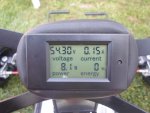
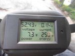
The contactor carries the flowing current, from the battery pack to the motor/controller
...but, also, can sever that flowing current, when the relay is "switched off"
(like in a "run away" situation, or when the low voltage threshold has been reached)
A precharge circuit is basically just a resistor, connected across the terminals of the contactor, that only allows a small amount of current flow thru at a time.
It's job/function to slowly fill up the capacitators, in the speed controller, so that they don't get "slammed" with a huge "inrush" of current when the contactor is first switched on.
* An additional benefit of adding a precharge circuit to this system, besides protecting the capacitators, is that by "equalizing" the voltage of the batt pack & the capacitators before the contactor is switched on, it would/should not have to deal with a huge "inrush" of current, thus protecting the contacts inside of the contactor.

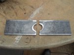
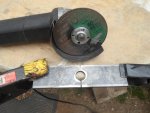
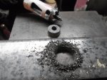
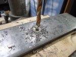
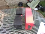
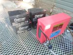
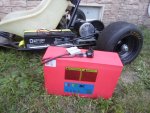
Let's see what I can "conjure up"


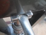
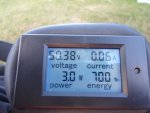
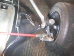
 SAM_5838.JPG308.2 KB · Views: 4
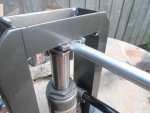
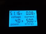
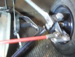
 SAM_5839.JPG319.1 KB · Views: 4
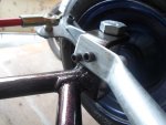
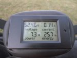
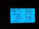
 SAM_5840.JPG316.8 KB · Views: 3
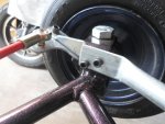
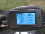
 SAM_5843.JPG316.1 KB · Views: 2
 SAM_5845.JPG310.3 KB · Views: 3