Functional Artist
Well-known member
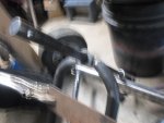
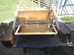
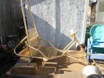
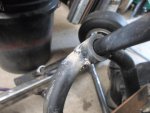
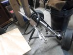
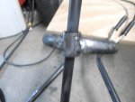
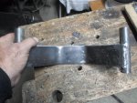
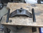
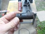
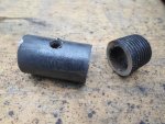
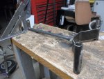
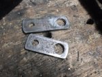
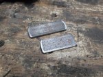
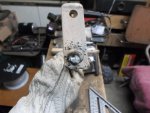
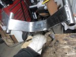
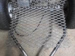
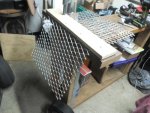
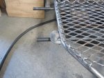
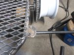
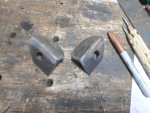
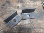
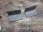
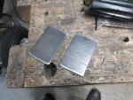
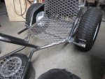
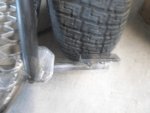
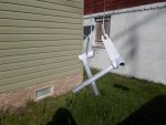
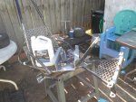
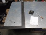
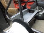
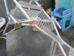
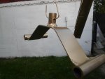
After splitting the steering support
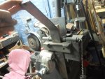
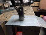
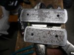
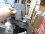
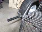
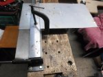
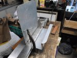
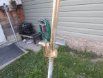
used a piece of scrap steel & vise grips to help hold & align the pieces
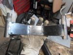
a little tack weld here
a little tack weld there
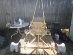
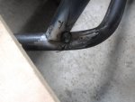
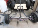
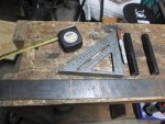
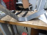
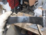
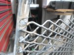
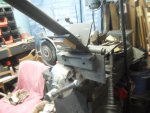
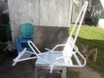
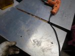
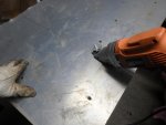
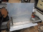
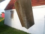
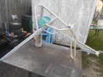
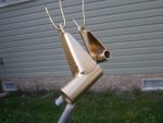
Then double check everything
...measurements
...alignment
...angles
...& even by eye (gotta look good)
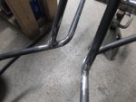
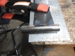
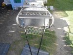
used a piece of scrap steel & vise grips to help hold & align the pieces
a little tack weld here
a little tack weld there
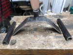
Then double check everything
...measurements
...alignment
...angles
...& even by eye (gotta look good)
Attachments
-
 SAM_6293.jpg205.1 KB · Views: 5
 -
 SAM_6296.jpg204.4 KB · Views: 6
 -
 SAM_6298.jpg198.6 KB · Views: 6
 -
 SAM_6300.jpg230.8 KB · Views: 6
 -
 SAM_6302.jpg233.5 KB · Views: 6
 -
 SAM_6309.jpg271.8 KB · Views: 5
 -
 SAM_6307.jpg261.8 KB · Views: 5
 -
 SAM_6303.jpg184.6 KB · Views: 7


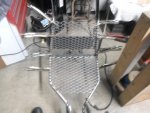


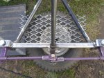


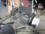
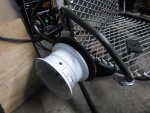

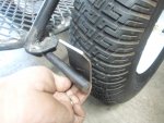
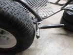
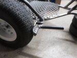
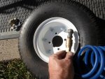
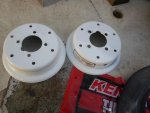


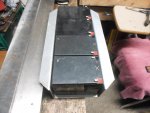

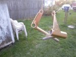
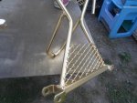
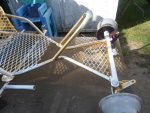
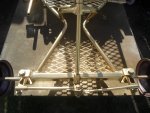
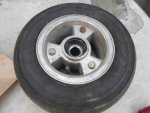
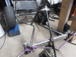
 Looking great though!! I like your braking system but the only down fall I see is that you are limited to that size tire for ever.