Sorry Paul. LOL
I thought it was kinda funny.
You just walked into it and I had to see how many lyrics I get out.
I was just wondering what Adele was doing on a go kart.
I must haved called a thousand times. LOL
https://www.youtube.com/watch?v=9h0Arg_-380
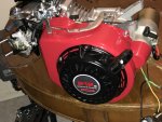
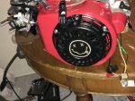
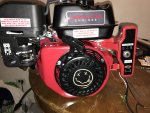
Anyway I tested the output of the Kohler stator's single wire output.
I tested the same way for DC and for AC. One multimeter lead on the stator wire and the other lead on bolt in the block.
First tested on the 20DCV scale and got nada.
Tested on the 200ACV scale on got ~ 29-30.
Next phase of testing will be to plug in the stator output to the key-box and find out if there is a diode somewhere in there.
If I am getting AC out of the single wire coil, then that brings me back to wanting to use a full wave rectifier/regulator.
Which still makes me wonder how I wire single wire AC (which I guess uses the block where it is mounted as "ground") to a rectifier (which also uses its mounting for DC ground).
I don't think I can have the same "ground" for AC and DC. And not sure I can isolate the AC and DC circuits.
The only way I can think to wire it would be the coil wire to an input lead on the rectifier. A wire from a block bolt to the other input lead. The positive DC output going to the battery. I think I need a wire from the negative side of the battery going to where the rectifier is mounted (connecting the battery negative to the DC negative output of the rectifier). I think this would mean I would have to isolate the battery/rectifier/DC circuitry from the engine block?????
Otherwise I've read about people unwinding the coil to get at the other lead. I suppose this is to get two output wires and not use the block as ground???
I am not a fan of circuits. I know very little. Which is why I wanted to do this project.
 41E2161E-1B7F-4078-A9BB-FFA164BAD4B9.jpg283.4 KB · Views: 8

")