I just hooked up the output of my coil to a full wave rectifier bridge rated for 4 amps. Open circuit I got 10VDC @ 1800 RPM and 31VDC @ 4600 RPM. Connected my 2 HiLight 18W LED's and they light nicely as I took several laps around my yard. Should have check loaded voltage. Kids will be happy. They do flicker a bit and thinking about installing a 1 Farad cap I've got laying around from my car audio days. I highly doubt this setup was designed to charge a battery on an engine that doesn't have a fixed governed speed like a genny, etc. When looking at DC/DC converters you have a catch 22 going on. We want a fixed voltage output which is between the input min and max. Might be able to cascade a boost with a buck but I'm not going there. Next: Governor removal on Sunday but no 18 lb springs.
You are using an out of date browser. It may not display this or other websites correctly.
You should upgrade or use an alternative browser.
You should upgrade or use an alternative browser.
Predator Lighting Coil
- Thread starter bob58o
- Start date
bob58o
SuckSqueezeBangBlow
I just hooked up the output of my coil to a full wave rectifier bridge rated for 4 amps. Open circuit I got 10VDC @ 1800 RPM and 31VDC @ 4600 RPM. Connected my 2 HiLight 18W LED's and they light nicely as I took several laps around my yard. Should have check loaded voltage. Kids will be happy. They do flicker a bit and thinking about installing a 1 Farad cap I've got laying around from my car audio days. I highly doubt this setup was designed to charge a battery on an engine that doesn't have a fixed governed speed like a genny, etc. When looking at DC/DC converters you have a catch 22 going on. We want a fixed voltage output which is between the input min and max. Might be able to cascade a boost with a buck but I'm not going there. Next: Governor removal on Sunday but no 18 lb springs.
So you are going to run the leds directly from the rectifier?
They are ok with 30 -40 Volt input?
So you are going to run the leds directly from the rectifier?
They are ok with 30 -40 Volt input?
Yes I ran them from the rectifier. The lights are rated 9-30VDC. Might be a problem once I hit 5K without the gov but I also need to check loaded voltage, probably a lot less. At $13.30 a set of lights no great loss.
bob58o
SuckSqueezeBangBlow
Volts across battery vs RPM
Shows with just the light and with the light and pump ON.
With no charging, battery was 13.55 Volts.
With no charging and the 18 watt light, across the battery read 13.05 Volts.
With no charging and the (1 amp) fuel pump PLUS the 18 watt light, across the battery read 12.9 Volts.
Then I started the engine and ran at a few different RPMs.
Checked with BOTH Pump AND Light ON.
Then Checked with just the Light ON, Pump OFF.
You can see around 3600 RPM, the voltage is around 14.2- 14.4. Like somebody thought about it.
Attachments
-
 data rpm volts.jpg43.7 KB · Views: 17
Just to reiterate my flywheel has 2 magnets on the inside and I have 2 coils with 2 wires coming out:
After that post I checked my DC "rippled" voltage from my rectifier loaded to 36 watts. 5.5 VDC @ Idle and 20VDC @ 4500 RPM.
So 30 VDC was at 4500 RPM unloaded, never saw 40. Loaded to 36W is now 20 VDC. Well within the upper range and I was surprised on how well they ran on 5.5 VDC with lights rated for 9 VDC min.
Bob, I reread the first 3 pages of this thread and still couldn't figure out what you settled on. It's probably in your engine build tread but anybody doing a search on Predator lighting is going to find this tread first, probably. The graph above shows 13-13.5 @ idle compared to my 5.5. Do you have only 2 magnets inside the flywheel? One coil with 1 wire or 2 coils with 2 wires? Sorry for beating this horse, it's almost dead. I'm thinking you have a higher voltage charging coil intended to be used with a battery for infrequent use (starter, clutch,etc) where I have a higher current lighting coil intended for continuous use (headlight).
My 1 farad cap I was going to try is only rated for 20 VDC so I have to buy one. This is a must do for me as I read LED lifespan is greatly diminished by high ripple current. 1/2 farad will reduce ripple voltage to .13 volts at 60 Hz (3600 RPM). That will be pretty smooth.
V ripple= ((Current * Period) / Capacitance)
I just hooked up the output of my coil to a full wave rectifier bridge rated for 4 amps. Open circuit I got 10VDC @ 1800 RPM and 31VDC @ 4600 RPM. Connected my 2 HiLight 18W LED's and they light nicely as I took several laps around my yard. Should have check loaded voltage.
After that post I checked my DC "rippled" voltage from my rectifier loaded to 36 watts. 5.5 VDC @ Idle and 20VDC @ 4500 RPM.
So you are going to run the leds directly from the rectifier?
They are ok with 30 -40 Volt input?
So 30 VDC was at 4500 RPM unloaded, never saw 40. Loaded to 36W is now 20 VDC. Well within the upper range and I was surprised on how well they ran on 5.5 VDC with lights rated for 9 VDC min.
You can see around 3600 RPM, the voltage is around 14.2- 14.4. Like somebody thought about it.
Bob, I reread the first 3 pages of this thread and still couldn't figure out what you settled on. It's probably in your engine build tread but anybody doing a search on Predator lighting is going to find this tread first, probably. The graph above shows 13-13.5 @ idle compared to my 5.5. Do you have only 2 magnets inside the flywheel? One coil with 1 wire or 2 coils with 2 wires? Sorry for beating this horse, it's almost dead. I'm thinking you have a higher voltage charging coil intended to be used with a battery for infrequent use (starter, clutch,etc) where I have a higher current lighting coil intended for continuous use (headlight).
My 1 farad cap I was going to try is only rated for 20 VDC so I have to buy one. This is a must do for me as I read LED lifespan is greatly diminished by high ripple current. 1/2 farad will reduce ripple voltage to .13 volts at 60 Hz (3600 RPM). That will be pretty smooth.
V ripple= ((Current * Period) / Capacitance)
bob58o
SuckSqueezeBangBlow
J
Bob, I reread the first 3 pages of this thread and still couldn't figure out what you settled on. It's probably in your engine build tread but anybody doing a search on Predator lighting is going to find this tread first, probably. The graph above shows 13-13.5 @ idle compared to my 5.5. Do you have only 2 magnets inside the flywheel? One coil with 1 wire or 2 coils with 2 wires? Sorry for beating this horse, it's almost dead. I'm thinking you have a higher voltage charging coil intended to be used with a battery for infrequent use (starter, clutch,etc) where I have a higher current lighting coil intended for continuous use (headlight).
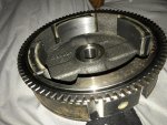
I got the parts for the Kohler CH270 3 AMP System. There is also a CH270 10 AMP System.
Here is the flywheel and here is the stator.
There is a diode in the wire coming from the Honda Clone Keybox that I used for half wave rectification. The AC Voltage I measured earlier in testing was the output of the stator wire (no diode).
3 magnets (on the inside).
2 coils.
1 wire.
And a Partridge in a Pear-Tree.
So I guess my coils are wired in series? Providing Higher Voltage?
Where yours may be wired in Parallel? Providing Higher Current?
Attachments
-
 flywheelk.jpg472.7 KB · Views: 2
 -
 statork.gif82.4 KB · Views: 2
bob58o
SuckSqueezeBangBlow
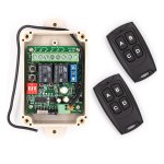
I thought push button start would be cool.
How about remote push button start? That would be something.
https://www.amazon.com/Solidremote-..._rd_t=40701&psc=1&refRID=8QKRHEP7W63HNX61HCGG
What could ever go wrong with that?
Bob: "Hey guys, look out the window!!!"
Guys: "Where is you minibike going?"
How about remote push button start? That would be something.
https://www.amazon.com/Solidremote-..._rd_t=40701&psc=1&refRID=8QKRHEP7W63HNX61HCGG
What could ever go wrong with that?
Bob: "Hey guys, look out the window!!!"
Guys: "Where is you minibike going?"
Attachments
-
 remote.jpg254.1 KB · Views: 1
SimpleNoob
New member
- Messages
- 2
- Reaction score
- 0
@Bob sir thank you for all this information. Unfortunately after reading it all and trying to comprehend what I read
My brain is fried.
No but really I could only grasp about 47% of the material so I imagine this is going to be a great under taking on my part.
Wish me luck
My brain is fried.
No but really I could only grasp about 47% of the material so I imagine this is going to be a great under taking on my part.
Wish me luck
You can take a clone flywheel and the coils and mount them on a predator. I've never tried the hemi, I don't own one.
Is it a 100% match? I don't know, but after sliding onto the key in the keyway, and torquing down to 65-70 FT lbs, it's not going anywhere, and doesn't wobble or anything.
Would I run it at 10,000 rpms? maybe not, But I will tell you it's just fine for everyday normal use.
I've done it for years now.
I don't care what the experts say, it works.
bob58o
SuckSqueezeBangBlow
The clone flywheel will not work on a hemi, but has been proven to work on non-hemis, even though the flywheels are supposedly slightly different. I've heard many people say that they haven't had any issues running a clone flywheel on a non-hemi predator. ARC says the taper is slightly different but have still said that many people have run without issues, but claim that some have had issues running a clone flywheel on a non-hemi.
---------- Post added at 11:42 AM ---------- Previous post was at 11:37 AM ----------
Ask me questions if you want. You can ask in this thread. Unfortunately google points a lot of people to this thread and it would be nice to be able to clear some of this mess up so this thread might actually help people.
The questions most people have is about the output of their coil and how to rectify/regulate it. The things I don't know much about are the types of coils, their outputs, and how to rectify / regulate them. LOL
---------- Post added at 11:46 AM ---------- Previous post was at 11:42 AM ----------
That makes two of us.

---------- Post added at 11:42 AM ---------- Previous post was at 11:37 AM ----------
@Bob sir thank you for all this information. Unfortunately after reading it all and trying to comprehend what I read
No but really I could only grasp about 47% of the material so I imagine this is going to be a great under taking on my part.
Wish me luck
Ask me questions if you want. You can ask in this thread. Unfortunately google points a lot of people to this thread and it would be nice to be able to clear some of this mess up so this thread might actually help people.
The questions most people have is about the output of their coil and how to rectify/regulate it. The things I don't know much about are the types of coils, their outputs, and how to rectify / regulate them. LOL
---------- Post added at 11:46 AM ---------- Previous post was at 11:42 AM ----------
My brain is fried.
That makes two of us.
bob58o
SuckSqueezeBangBlow
My plan is to use a 4 wire rectifier / regulator. One of the AC inputs comes from the output wire of the stator. The stator lone output wire delivers AC. The stator is “grounded” to the block, so I plan on having the other AC input terminal on the R/R also grounded to the block.
The DC+ output goes to the +terminal of the battery. The DC- output does to the -terminal on the battery.
To isolate the AC and DC, the battery will not be grounded to the frame and all accessories will have “ground” wires going back to the -terminal on the battery.
The charging system is a 36 watt system. I wanted to use this rectifier. The description says this one puts out enough voltage to charge the battery, but others just say 12V.
This is a brand new Voltage Regulator Rectifier fit for motorcycle and boat motors, DIY engines and so on. The rectifier outputs about DC14.5 voltage can charge for 12v lead acid battery and supply power for 12v bulb and so on. The rectifier comes with free wire adapter connect cable.
Specifications:
Fit 12V Battery, Bulb, Light and so on
Color Available: Black
AC Input Voltage: 20-60V
Unloading Output Voltage (Idling): 12.5~13v±0.5v
Charging Output Current: 0 - 4A
With Battery Charging Voltage:14~14.6±0.5V
Working Temperature: -20℃to 60℃
Cable Wire: Red to Battery +, Green to Battery -, Yellow and Pink AC input, connect to magneto coil.
Rectifier 4 Wires Voltage Regulator Replacement for Boat Motor Mercury ATV GY6 50 150cc Scooter Moped JCL NST TAOTAO https://www.amazon.com/dp/B00ZI7U8R...abc_7M38V894VVWDYZS90A6W?_encoding=UTF8&psc=1
bob58o
SuckSqueezeBangBlow
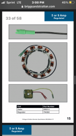
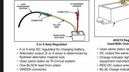
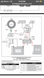
I may have made progress with my research. What’s up with this Briggs Charging system? Seems to have common neutral / ground for AC and DC. Seems to use a two wire rectifier regulator that simply replaces an inline diode (when regulating an unregulated system).
Section 15 (page 33 of 58)
2 wire rectifier regulator
Tech Service Manual for Briggs Charging systems
Section 15 (page 33 of 58)
2 wire rectifier regulator
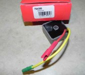
Briggs & Stratton Regulator Part No. 794360
Briggs & Stratton Regulator Part No. 794360,Briggs Stratton Ignition Coil,794360
www.smallenginesuppliers.com
Tech Service Manual for Briggs Charging systems
Attachments
-
 CC04DCFE-4125-4D28-9C2A-BFF2E8BE21F4.png286.1 KB · Views: 5
 -
 189BB2C2-25B7-472C-9204-10638CC609EE.png545 KB · Views: 4
 -
 161BA731-8D91-4C2D-9F98-041250188C87.jpeg66.2 KB · Views: 5
 -
 747BD5A2-7A6B-4611-8113-A316BD02557B.png257.6 KB · Views: 5
 -
 8FC20546-802F-4871-8413-1A6A7F5CB153.png280.8 KB · Views: 6
bob58o
SuckSqueezeBangBlow
I asked what was going on with this 5/9A regulated Briggs system using a single wire stator. I asked about having the engine block as a common ground/neutral for both AC and DC. The answer I have been most comfortable with is below....
“It's all about the configuration of the rectifier.
With a half wave rectifier, only the positive-going half-cycles of the AC from the stator deliver current into the battery. Therefore although the stator voltage is AC, the current is pulsating DC. Considering the rectifier and stator coil as a unit, the blocked negative half-cycles are never seen, i.e. there is arguably no AC system in operation at all. A pulsating DC source is charging a DC battery, of which the negative is grounded. The Briggs module contains a regulator but is still half-wave rectified, so nothing really changes. It needs to see ground to sense the battery voltage and operate its own electronics, but the charging current still passes unidirectionally from stator to battery and no AC circuit exists.
With a bridge rectifier comprising four diodes, both half-cycles of stator output are used to charge the battery, which can offer a higher charge rate from a given stator. Due to the action of the bridge rectifier, the polarity of the stator coil and the DC system reverse relative to each other once per cycle. Therefore they cannot share a common terminal i.e. the engine block, as the polarities would conflict on the negative half-cycles.
In theory it doesn't matter whether the AC or DC side of the bridge rectifier has one wire grounded.; a 1-wire block-return stator would work with a fully insulated DC system, and a 1-wire block-return starter would work with a fully insulated 2-wire stator. In practice the latter is much more practical, as there is only the stator coil on the AC side to insulate, but multiple devices on the DC side that can benefit from having a block ground connection.”