Torsk (Backbone Chassis) Kart

Status
Not open for further replies.

Functional Artist

Well-known member
Messages
5,353
Reaction score
2,841
Location
Toledo, Ohio
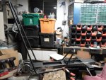
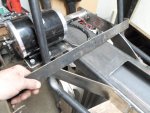
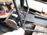
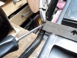
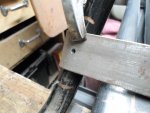
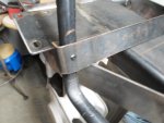
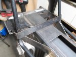
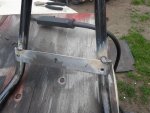
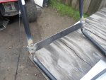
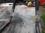
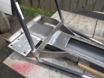
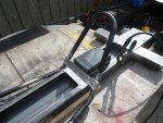
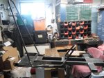
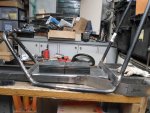
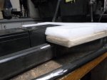
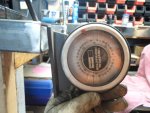
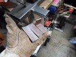
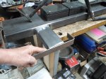
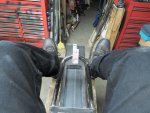
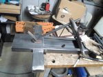
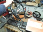
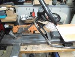
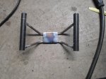
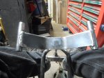
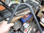
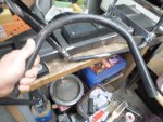
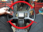
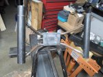
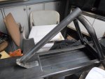
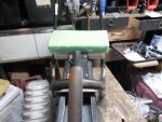
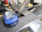
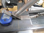
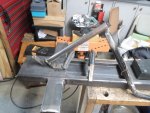
Placed the cockpit on the bench, over the backbone & double checked everything again

Everything still seems to line up pretty good :thumbsup:

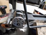
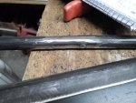
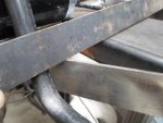
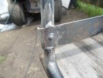
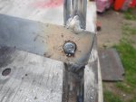
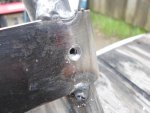
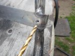
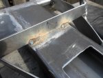
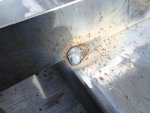
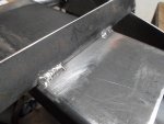
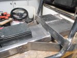
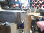
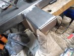
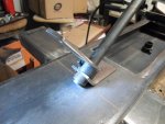
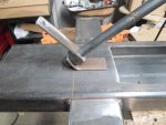
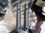
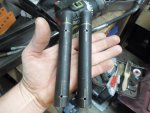
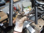
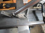
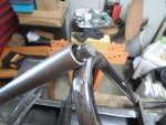
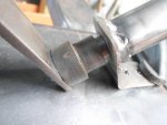
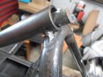
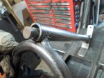
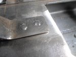
So, cleaned up the connections & welded a nice bead around both of 'em

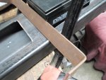
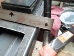
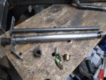
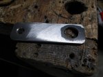
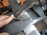
Removed the "pin" screws & drilled thru the outer layer of pipe to a 1/4"

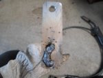
That way I could put a good "inner" spot weld, to help "lock 'em in from the inside"
...& fill up the holes too

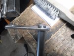
Then, cleaned 'er up a bit

I'm likin' the way it's coming along :2guns:
 

Attachments

  • SAM_9384.jpg
    SAM_9384.jpg
    340.5 KB · Views: 5
  • SAM_9385.jpg
    SAM_9385.jpg
    249 KB · Views: 3
  • SAM_9388.jpg
    SAM_9388.jpg
    286.5 KB · Views: 3
  • SAM_9387.jpg
    SAM_9387.jpg
    282.5 KB · Views: 3
Functional Artist

Well-known member
Messages
5,353
Reaction score
2,841
Location
Toledo, Ohio
Next, we gotta figure out where, exactly, is the cockpit gonna be positioned
...& how is it gonna be attached?

We know for sure (kinda) that it needs to be
...centered over the backbone chassis
...& as far back as possible but, still leaving adequate room for motor adjustment

As for attachment

I could just weld some short sections of pipe in between the backbone & the cockpit
(in all (4) corners)
...but, that's only a 2D (2 dimensional) connection & wouldn't be very structurally sound

There won't ever be very much weight pulling down on the cockpit
...but, without a 3D (3 dimensional) connection (some type of triangulation or structural back up) in a roll over situation & it would probably just snap off :ack2:

Then, I thought about using a couple of pieces of 1/4" x 1" flat steel
...just welded to the bottom of the backbone
...extending out on each side & have the cockpit sit in top & welded to them

Again, not too structural, still only 2D

Then I thought, how about putting the cross bars on angles :thumbsup:

In the rear across the backbone & the bottom of the seatback
...angled toward the rear
& in the front across the backbone & the bottom of the steering support
...angled toward the front

Yea, that looks better & stronger :2guns:

It looks like this set up will
...give many good welding (junctions) on the backbone & the cockpit
...should allow the backbone chassis & the cockpit to twist/flex together
...& ain't gonna snap off on a roll over :cheers2:
 

Attachments

  • SAM_9396.jpg
    SAM_9396.jpg
    242.9 KB · Views: 1
  • SAM_9394.jpg
    SAM_9394.jpg
    281.9 KB · Views: 1
  • SAM_9391.jpg
    SAM_9391.jpg
    213.6 KB · Views: 1
  • SAM_9389.jpg
    SAM_9389.jpg
    261.4 KB · Views: 1
  • SAM_9390.jpg
    SAM_9390.jpg
    251.4 KB · Views: 1

Functional Artist

Well-known member
Messages
5,353
Reaction score
2,841
Location
Toledo, Ohio
The pieces of 1/8" steel strips had 90* bends on one end

The bends wrapped around so nicely that instead of cutting them off
I wanted them on both ends

So, I marked both pieces ~1' longer than necessary & put 90* bends on the other ends too :thumbsup:

Then, I drilled & used small screws to "pin" the bars in place for welding :2guns:
 

Attachments

  • SAM_9420.jpg
    SAM_9420.jpg
    300.6 KB · Views: 1
  • SAM_9424.jpg
    SAM_9424.jpg
    263.7 KB · Views: 1
  • SAM_9423.jpg
    SAM_9423.jpg
    218.3 KB · Views: 1
  • SAM_9416.jpg
    SAM_9416.jpg
    211.6 KB · Views: 1
  • SAM_9415.jpg
    SAM_9415.jpg
    261.8 KB · Views: 1

Functional Artist

Well-known member
Messages
5,353
Reaction score
2,841
Location
Toledo, Ohio
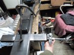
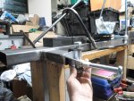
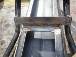
I started off by just welding the cross bars onto the cockpit
(they are "pinned" so I am not worried about them coming out of adjustment)

A quick bead (um blob) across the top & bottom on all (4) corners

Then, I removed the "pin" screws
...drilled the outer layer of steel out to 1/4"
...spot welded/filled them in
...& a little clean up :thumbsup:
 

Attachments

  • SAM_9470.jpg
    SAM_9470.jpg
    350.3 KB · Views: 1
  • SAM_9472.jpg
    SAM_9472.jpg
    358.9 KB · Views: 1
  • SAM_9473.jpg
    SAM_9473.jpg
    393.8 KB · Views: 1
  • SAM_9495.jpg
    SAM_9495.jpg
    283.5 KB · Views: 1
  • SAM_9490.jpg
    SAM_9490.jpg
    269.2 KB · Views: 1
  • SAM_9489.jpg
    SAM_9489.jpg
    392.2 KB · Views: 1
  • SAM_9483.jpg
    SAM_9483.jpg
    243.4 KB · Views: 1
  • SAM_9485.jpg
    SAM_9485.jpg
    337.9 KB · Views: 1

Functional Artist

Well-known member
Messages
5,353
Reaction score
2,841
Location
Toledo, Ohio
Marriage time
...time to make two as one

The cockpit sits nicely on the backbone
...except for the trailing arms (remember they are a little wider than the backbone itself)

A couple of quick notches with the grinder & no more problem :thumbsup:

Centered the cockpit, on the backbone chassis
...double checked the motor (rear) & battery (front) clearances (for the last time)
...this is where the "or forever hold your peace" part comes in

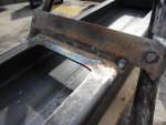
A couple of decent welds in the rear
...then a nice long bead in the front (I was on a roll) :2guns:
 

Attachments

  • SAM_9506.jpg
    SAM_9506.jpg
    401.6 KB · Views: 1
  • SAM_9505.jpg
    SAM_9505.jpg
    312.7 KB · Views: 1
  • SAM_9504.jpg
    SAM_9504.jpg
    290.8 KB · Views: 1
  • SAM_9498.jpg
    SAM_9498.jpg
    383.9 KB · Views: 1
  • SAM_9497.jpg
    SAM_9497.jpg
    397.3 KB · Views: 1
  • SAM_9507.jpg
    SAM_9507.jpg
    312.8 KB · Views: 1
  • SAM_9512.jpg
    SAM_9512.jpg
    242 KB · Views: 1
  • SAM_9515.jpg
    SAM_9515.jpg
    250.3 KB · Views: 3
Functional Artist

Well-known member
Messages
5,353
Reaction score
2,841
Location
Toledo, Ohio
Back to the tires, again

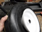
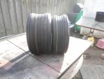
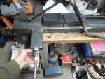
I finally got one of the 13 x 5.00/6 tires "blowed up" on the rim
...it was a total PITA :ack2:

It looked like a wheel barrow tire
(imagine just mounting an inner tube on a rim & inflating it)

Yup, it looked kinda like that :smiley_omg:
(I thought I had some pics but, can't find them now)

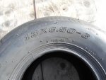
So, I got a couple of 13 x 6.50/6 ribbed tires
...they look much better :thumbsup:

The 13 x 5.00/6 ribbed tires should work in the front
...on narrower front rims of course :cheers2:
 

Attachments

  • SAM_9379.jpg
    SAM_9379.jpg
    220.9 KB · Views: 1
  • SAM_9382.jpg
    SAM_9382.jpg
    195.8 KB · Views: 1
  • SAM_9519.jpg
    SAM_9519.jpg
    319.7 KB · Views: 1
  • SAM_9522.jpg
    SAM_9522.jpg
    330.6 KB · Views: 1
  • SAM_9527.jpg
    SAM_9527.jpg
    290.9 KB · Views: 1

Functional Artist

Well-known member
Messages
5,353
Reaction score
2,841
Location
Toledo, Ohio
What do we do next? (on the chassis, that is)
...there is plenty of other stuff (the guts) left to do

So, we still need
...the steering (steering wheel, shaft, spindles etc.)
...& a seat

But, there are some variables, that need to work together, to consider or "keep in mind"

What type of steering wheel (style, dimensions etc.)
...which will affect, the steering shaft angle & help dictate it's mounting (above the steering support or below)

But, also what type of seat & it's mounting method
...because the seats dimensions will also affect or influence the choice of steering wheel & shaft mounting method

* The seat needs to clear (sit above) the rear battery so, we can't just "throw a cushion" on this one

More to come :thumbsup:
 

Attachments

  • SAM_9536.jpg
    SAM_9536.jpg
    330 KB · Views: 0
  • SAM_9535.jpg
    SAM_9535.jpg
    284.5 KB · Views: 1
  • SAM_9533.jpg
    SAM_9533.jpg
    311.1 KB · Views: 1
  • SAM_9531.jpg
    SAM_9531.jpg
    311.4 KB · Views: 0

Functional Artist

Well-known member
Messages
5,353
Reaction score
2,841
Location
Toledo, Ohio
Have been workin' on/thinkin' about the seat situation

There is not much room behind the rear batteries, ~5"
...& the batteries stick up out of the backbone ~2"

So, maybe
...riding lawn mower style (with springs?)
...or just stuff some foam rubber back there

Naw, not feelin' it :ack2:

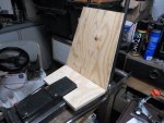
How about a custom "wrap around the battery" seat
...standard plywood seat bottom/back
...a little bit of foam rubber
...& some vinyl

Yup, I like that better :thumbsup:

Before padding & upholstery, I rounded & smoothed the edges a bit
...& the rear bearing spacers too :cheers2:
 

Attachments

  • SAM_9580.jpg
    SAM_9580.jpg
    325.3 KB · Views: 0
  • SAM_9581.jpg
    SAM_9581.jpg
    278.2 KB · Views: 0
  • SAM_9604.jpg
    SAM_9604.jpg
    224.2 KB · Views: 0
  • SAM_9587.jpg
    SAM_9587.jpg
    248.3 KB · Views: 0
  • SAM_9585.jpg
    SAM_9585.jpg
    217.7 KB · Views: 0
  • SAM_9571.jpg
    SAM_9571.jpg
    264.7 KB · Views: 0
  • SAM_9570.jpg
    SAM_9570.jpg
    361.8 KB · Views: 0
  • SAM_9607.jpg
    SAM_9607.jpg
    253.2 KB · Views: 0
  • SAM_9608.jpg
    SAM_9608.jpg
    307 KB · Views: 0

Functional Artist

Well-known member
Messages
5,353
Reaction score
2,841
Location
Toledo, Ohio
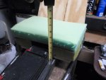
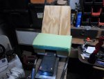
First, tried a layer of 2" foam rubber padding
...but, when I sat on it, I could still feel the battery

So, I tried (2) layers of 2" padding
...could still feel it

(3) layers of 2" padding did the trick
...but, it was 6" thick :smiley_omg:

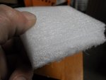
Then, I tried some of this 1" closed cell foam rubber stuff (like a pool noodle)

It is kinda springy
...but, it does not give (collapse) as much as foam rubber

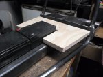
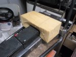
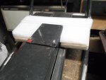
The "white" layer on top of the plywood brings it up just about even with the top of the battery
...& a 2" layer of the foam rubber will top it off nicely :cheers2:
 

Attachments

  • SAM_9616.jpg
    SAM_9616.jpg
    227.7 KB · Views: 0
  • SAM_9612.jpg
    SAM_9612.jpg
    216.4 KB · Views: 0
  • SAM_9619.jpg
    SAM_9619.jpg
    167.7 KB · Views: 0
  • SAM_9620.jpg
    SAM_9620.jpg
    224.8 KB · Views: 0
  • SAM_9621.jpg
    SAM_9621.jpg
    217.8 KB · Views: 1

Functional Artist

Well-known member
Messages
5,353
Reaction score
2,841
Location
Toledo, Ohio
I pretty much have the seat situation figured out :thumbsup:
...placement, dimensions & such

Just have to make the cover
...but, it's kinda complicated
...& I wanna do it right
...so, I'm not gonna rush it :cheers2:

So then, I went back to workin' on the steering

First I boxed off the ends of the front axle with some 1/8" x 1 3/4" steel
...on a bit of an angle :2guns:
 

Attachments

  • SAM_9554.jpg
    SAM_9554.jpg
    217.9 KB · Views: 1
  • SAM_9551.jpg
    SAM_9551.jpg
    266.4 KB · Views: 1
  • SAM_9541.jpg
    SAM_9541.jpg
    244.4 KB · Views: 0
  • SAM_9542.jpg
    SAM_9542.jpg
    280.5 KB · Views: 0
  • SAM_9538.jpg
    SAM_9538.jpg
    298.7 KB · Views: 0

Functional Artist

Well-known member
Messages
5,353
Reaction score
2,841
Location
Toledo, Ohio
I started off with some 5/8" steel rod
...a couple of grease able nylon bushings
...a Craftsman riding lawn mower steering wheel
...a 1/8" x 3" "steering lever"
...& a mounting "foot"

The 'steering lever" seemed to have too much throw
...so, I made a few others (1/8" x 1 1/2" & 1/8" x 2 1/2")
 

Attachments

  • SAM_9573.jpg
    SAM_9573.jpg
    294.6 KB · Views: 1
  • SAM_9572.jpg
    SAM_9572.jpg
    292.7 KB · Views: 0
  • SAM_9569.jpg
    SAM_9569.jpg
    270.5 KB · Views: 0
  • SAM_9568.jpg
    SAM_9568.jpg
    258.6 KB · Views: 1
  • SAM_9565.jpg
    SAM_9565.jpg
    241.1 KB · Views: 0
  • SAM_9574.jpg
    SAM_9574.jpg
    290 KB · Views: 0
  • SAM_9575.jpg
    SAM_9575.jpg
    303.4 KB · Views: 0
  • SAM_9628.jpg
    SAM_9628.jpg
    225.5 KB · Views: 0

Functional Artist

Well-known member
Messages
5,353
Reaction score
2,841
Location
Toledo, Ohio
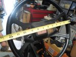
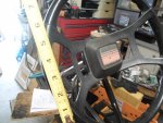
The steering wheel is NOT workin' for me :ack2:
...too big? gawdy?
...plus I want/need to use a thumb throttle

Bounced around a couple of ideas
...but, I'm tryin' to stay away from "handle bars"

I liked the "butterfly style" steering wheel that I made for the !Arriba! kart last fall
...but, not the grip so much

So, I'm thinkin' an "open grip" "butterfly style" steering wheel :thumbsup:
 

Attachments

  • SAM_9693.jpg
    SAM_9693.jpg
    328.1 KB · Views: 0
  • SAM_6325.jpg
    SAM_6325.jpg
    256.2 KB · Views: 0
  • SAM_9661.jpg
    SAM_9661.jpg
    290.2 KB · Views: 0
  • SAM_9660.jpg
    SAM_9660.jpg
    272.4 KB · Views: 0

Functional Artist

Well-known member
Messages
5,353
Reaction score
2,841
Location
Toledo, Ohio
I kinda liked the center part of the steering wheel
...so, I used it for (rough) measurements

To have ample room to "grip it good" & room to mount a thumb throttle
...it looks like we need ~6'

So, the "butterfly style" steering wheel is
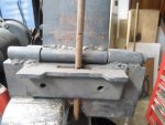
...(2) 6" pieces of water pipe (marked & drilled to matching specs)
...(2) 12" pieces of 3/8" rod (custom bent to matching specs also)
...& a piece of 1/8" x 2" steel

Yup, that should work :thumbsup:
 

Attachments

  • SAM_9672.jpg
    SAM_9672.jpg
    252.6 KB · Views: 0
  • SAM_9671.jpg
    SAM_9671.jpg
    278.7 KB · Views: 0
  • SAM_9662.jpg
    SAM_9662.jpg
    262.4 KB · Views: 0
  • SAM_9679.jpg
    SAM_9679.jpg
    265.3 KB · Views: 1
  • SAM_9677.jpg
    SAM_9677.jpg
    285.4 KB · Views: 0
  • SAM_9675.jpg
    SAM_9675.jpg
    252.2 KB · Views: 0
  • SAM_9669.jpg
    SAM_9669.jpg
    261.1 KB · Views: 0
  • SAM_9668.jpg
    SAM_9668.jpg
    236.5 KB · Views: 0
  • SAM_9682.jpg
    SAM_9682.jpg
    274.6 KB · Views: 0

ezcome-ezgo

G'me sumthin to write on
Messages
5,917
Reaction score
2,879
Location
Atlanta, GA
What is you just cut away the red part of the tractor wheel?
 

Attachments

  • SAM_9573.jpg
    SAM_9573.jpg
    409.2 KB · Views: 0

Functional Artist

Well-known member
Messages
5,353
Reaction score
2,841
Location
Toledo, Ohio
What is you just cut away the red part of the tractor wheel?

I thought about it :thumbsup:

But, I would of had to leave a bit extra stickin' up & then whittled it down (to add a piece of pipe) for the thumb throttle & secure it

...& the mounting stub (coming off of the bottom of the steering wheel) was kinda wonky/wobbly :ack2:

Plus, IMHO it just didn't go with the style of the kart :cheers2:

This one is much tighter & I think it looks "Bad Azz" :2guns:
 

Attachments

  • SAM_9713.jpg
    SAM_9713.jpg
    303.6 KB · Views: 1

Functional Artist

Well-known member
Messages
5,353
Reaction score
2,841
Location
Toledo, Ohio
Now, that we know the seat dimensions & steering wheel dimensions

Next, was to work on placement/aligning & getting the steering shaft mounted

I think, I'm gonna put the steering shaft inside of a protective tube
...in true backbone chassis style :thumbsup:

It wont add much extra weight
...& it'll look kool :2guns:

So, I bent a piece of 1/8" x 1 1/4" steel for the "foot" & welded it to the bottom of the steering shaft housing
...using a brass bushing to aid alignment (of the tube & the foot) during welding

Also welded the 1 1/2" steering lever to the bottom of the steering shaft
...leaving ~1/4" stickin' up (for "good" welding "penetration")
 

Attachments

  • SAM_9635.jpg
    SAM_9635.jpg
    236.6 KB · Views: 0
  • SAM_9634.jpg
    SAM_9634.jpg
    243.4 KB · Views: 0
  • SAM_9632.jpg
    SAM_9632.jpg
    238.8 KB · Views: 0
  • SAM_9631.jpg
    SAM_9631.jpg
    240.5 KB · Views: 0
  • SAM_9630.jpg
    SAM_9630.jpg
    245.8 KB · Views: 0
  • SAM_9649.jpg
    SAM_9649.jpg
    356.1 KB · Views: 1
  • SAM_9646.jpg
    SAM_9646.jpg
    191.9 KB · Views: 0
  • SAM_9642.jpg
    SAM_9642.jpg
    254.8 KB · Views: 0
  • SAM_9639.jpg
    SAM_9639.jpg
    311.7 KB · Views: 0
  • SAM_9637.jpg
    SAM_9637.jpg
    248.8 KB · Views: 0

Functional Artist

Well-known member
Messages
5,353
Reaction score
2,841
Location
Toledo, Ohio
Next is to get the steering assembly mounted on the kart

I drilled a couple of 1/4" "spot" welding holes in the "foot" (I'm kinda likin' this attachment method)

Also, I gotta keep it kool so I don't melt the lower nylon bushing, from the welding heat
...the way this is designed, the lower nylon bushing cannot be installed later

So, I slid the steering shaft & the nylon bushing down & as far away from the "foot" as possible (before welding)

First, welded (1) spot, securing the "foot" to the backbone
...then, checked temperature of the area around the bushing

Yup, still kool to the touch :thumbsup:

But, I don't want to "push it"
...so, while that was koolin', I moved up to the top & double checked alignment

Then, plopped a weld on each side
...securing the steering housing to the steering support (left the nylon bushing out of the top 'cause it can be installed later)

Then, went back to the bottom & welded the other spot, on the foot
...again checking temperature

I kinda like the end result of these "spot" welds, it leaves an "industrial" but, "clean" look & seems like a very strong connection too :2guns:

So, as a test, I not gonna weld along or around the edges of the "foot"
...to see if it holds up in this situation :cheers2:
 

Attachments

  • SAM_9698.jpg
    SAM_9698.jpg
    251.1 KB · Views: 0
  • SAM_9697.jpg
    SAM_9697.jpg
    233.9 KB · Views: 0
  • SAM_9696.jpg
    SAM_9696.jpg
    203.6 KB · Views: 0
  • SAM_9695.jpg
    SAM_9695.jpg
    229.8 KB · Views: 0
  • SAM_9694.jpg
    SAM_9694.jpg
    277.4 KB · Views: 1
  • SAM_9699.jpg
    SAM_9699.jpg
    217 KB · Views: 0
  • SAM_9701.jpg
    SAM_9701.jpg
    224.6 KB · Views: 0
  • SAM_9702.jpg
    SAM_9702.jpg
    233.5 KB · Views: 0
  • SAM_9706.jpg
    SAM_9706.jpg
    259.9 KB · Views: 0
  • SAM_9707.jpg
    SAM_9707.jpg
    213.7 KB · Views: 1
Status
Not open for further replies.
Top