Functional Artist
Well-known member
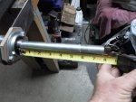
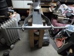
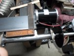
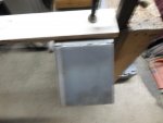
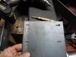
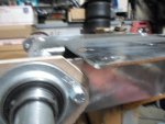
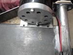
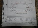
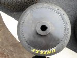
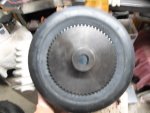
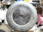
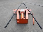
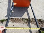
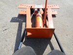
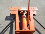
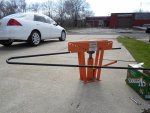
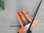
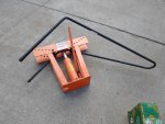
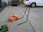
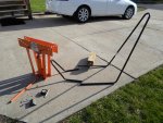
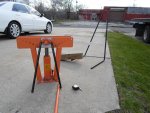
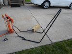
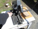
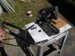
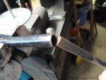
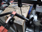
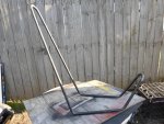
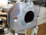
After a lot of cleaning
...smoothing all of the rough/sharp edges
...& removing all of the snot balls-n-such, from welding
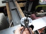
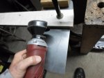
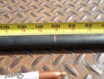
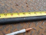
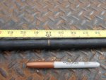
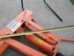
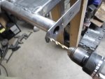
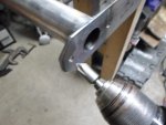
I ran a 5/16" drill bit thru the bolt holes to "be sure" their clean
...then, used a counter sink to chamfer the edges of the bolt holes a bit
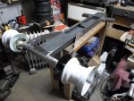
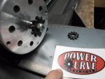
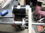
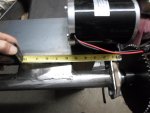
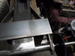
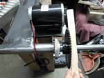
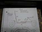
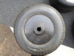
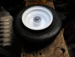
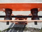
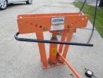
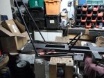
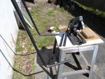
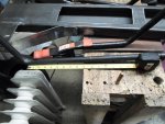
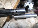
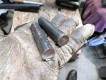
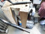
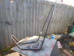
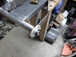
Bolted the bearings & spacers on
...just to see how everything looked
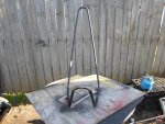
Looks pretty solid to me
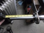
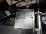
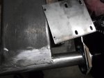
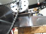
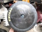
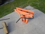
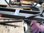
...smoothing all of the rough/sharp edges
...& removing all of the snot balls-n-such, from welding
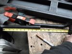
I ran a 5/16" drill bit thru the bolt holes to "be sure" their clean
...then, used a counter sink to chamfer the edges of the bolt holes a bit
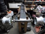
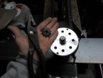
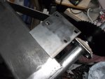
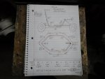
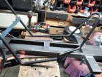
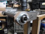
Bolted the bearings & spacers on
...just to see how everything looked
Looks pretty solid to me
Attachments
-
 SAM_8936.jpg220.3 KB · Views: 6
 -
 SAM_8937.jpg212.1 KB · Views: 4
 -
 SAM_8939.jpg195.5 KB · Views: 5
 -
 SAM_8943.jpg270.4 KB · Views: 4
 -
 SAM_8941.jpg235.8 KB · Views: 3