Torsk (Backbone Chassis) Kart

Status
Not open for further replies.

Functional Artist

Well-known member
Messages
4,403
Reaction score
1,678
Location
Toledo, Ohio
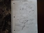
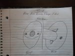
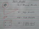
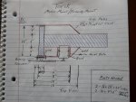
A little artwork while I was thinkin' :idea2:

I first contemplated using 4' round tube but, it seems like it would be easier to attach to flat surfaces
IDK it also just seems like round tube would twist more :ack2:

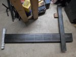
Then, I was leaning toward 4" x 4" x 1/8" square tube (~6.5 lbs. per ft.)
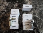
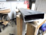
But, the 12V 12AH batteries, being 4" wide, would not fit inside a 4" square tube (~3 3/4" ID.)

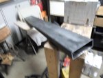
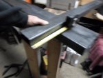
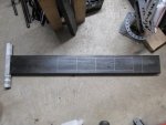
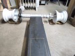
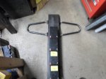
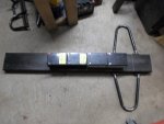
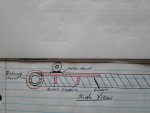
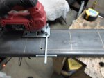
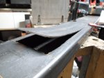
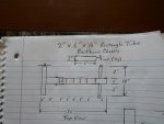
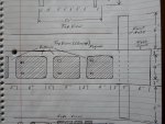
So, now I'm thinkin' 2" x 6" x 1/8" rectangular tube
...it's also ~6.5 lbs. per ft. (same as 4" x 4" square tube)
...but, I can cut out 4" (for the batteries) of the 6" wide tube & still have ~1" of steel wrap around to help maintain the "rigidity" of the backbone :thumbsup:

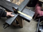
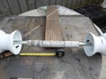
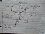
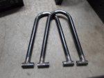
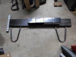
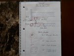
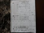
Front Axle, could be made of 1" x 3" x 1/8" steel, ~18" wide
...proportionally reduced from the backbone dimensions (2" x 6" to 1" x 3")
I am thinkin' of leaving the axle as (1) piece, cutting 1" x 3" slots on each side of the backbone & running it right thru :2guns:
...the left side axle stub would be 6", the backbone is 6" wide & the right side axle stub is 6" also (kinda of a 1:1:1 ratio)

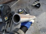
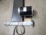
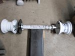
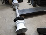
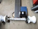
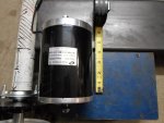
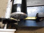
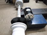
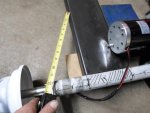
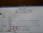
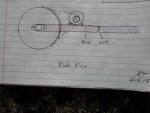
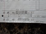
Rear Axle Housing, could be made of 2" x 1/8" round tube ~14" wide
...it could cap off the rear end of the backbone

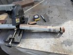
I am thinkin' of running the 1" axle thru it (like a true backbone chassis) & just having the bearings mounted right on the ends
...the left side axle housing would be 4", the backbone is (of course) 6" wide & the right side axle housing would be 4"
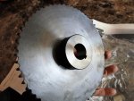
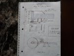
...the sprocket could be mounted between the bearing & the wheel, on one side
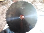
...& the brake rotor/drum on the other side :cheers2:

May do a mono-shock type suspension in the back

Still thinkin' on that one :cornut:
 

Attachments

  • USS Torsk.jpg
    USS Torsk.jpg
    244.2 KB · Views: 5
  • SAM_8440.jpg
    SAM_8440.jpg
    247.5 KB · Views: 4
  • SAM_8441.jpg
    SAM_8441.jpg
    261.6 KB · Views: 4
  • SAM_8442.jpg
    SAM_8442.jpg
    240.2 KB · Views: 3
  • SAM_8444.jpg
    SAM_8444.jpg
    303.3 KB · Views: 3
  • SAM_8445.jpg
    SAM_8445.jpg
    242.3 KB · Views: 3

Functional Artist

Well-known member
Messages
4,403
Reaction score
1,678
Location
Toledo, Ohio
Got my order from BMI Karts this morning (just ordered Thursday that was quick) :thumbsup:

I ordered some of the stuff that I usually don't or can't make myself

I asked about the DIYGK discount but, they said that they don't offer us a discount. (we need to work on that)

They still have the best deals, so...

ya, here's what I got :cheers2:

(1) Front spindle kit - (1) left & (1) right 4 1/2" x 5/8" (don't trust my weldin' skills that much)
(1) Rear Axle Bearing kit - for 1" axle (lighter than pillow blocks)
(1) Rear Axle - 1" x 32" with 1/4" full length key way (should be beefy enough for this concept)
(2) Lock Nuts - for 1" axle
(1) 12" of Key way stock - 1/4" x 1/4" (I should be able to cut all of the keys I need for this project) (1) for each rear wheel, (1) for the sprocket & (1) for the brake rotor/drum
(2) Rear Rims - 6" x 5" with a 1" bore & 1/4" key way

I also picked up (4) of these kool 10.5 x 4.5 x 6" Unilli "racing slicks" (they were on sale for ~$20.00 ea.)
Couldn't pass em' up :2guns:

But, wow they are low rider's/ground huggers

What's up with these directional arrows?
...If all arrows are pointing forward, the kool yellow letters won't be facing outward on one side :ack2:
 

Attachments

  • SAM_8376.jpg
    SAM_8376.jpg
    220.7 KB · Views: 2
  • SAM_8374.jpg
    SAM_8374.jpg
    282.4 KB · Views: 2
  • SAM_8372.jpg
    SAM_8372.jpg
    304.3 KB · Views: 2
  • SAM_8370.jpg
    SAM_8370.jpg
    309.7 KB · Views: 2
  • SAM_8369.jpg
    SAM_8369.jpg
    232.5 KB · Views: 4
  • SAM_8377.jpg
    SAM_8377.jpg
    246 KB · Views: 2
  • SAM_8378.jpg
    SAM_8378.jpg
    174.4 KB · Views: 2
  • SAM_8380.jpg
    SAM_8380.jpg
    230.1 KB · Views: 3
  • SAM_8385.jpg
    SAM_8385.jpg
    212.6 KB · Views: 3
  • SAM_8383.jpg
    SAM_8383.jpg
    185.2 KB · Views: 3

Functional Artist

Well-known member
Messages
4,403
Reaction score
1,678
Location
Toledo, Ohio

Attachments

  • SAM_8454.jpg
    SAM_8454.jpg
    271.3 KB · Views: 3
  • SAM_8457.jpg
    SAM_8457.jpg
    216 KB · Views: 3
  • SAM_8462.jpg
    SAM_8462.jpg
    248 KB · Views: 3
  • SAM_8460.jpg
    SAM_8460.jpg
    182.4 KB · Views: 3
  • SAM_8461.jpg
    SAM_8461.jpg
    199.1 KB · Views: 3

Functional Artist

Well-known member
Messages
4,403
Reaction score
1,678
Location
Toledo, Ohio
Picked some metal today :thumbsup:

Some 2" x 6" x 1/8" (11g.) rectangular tube for the backbone
&
Some 1 1/2" x 3" x 1/8" (11g.) rectangular tube for the front axle

I wanted 1" x 3" rec. tube for the front axle but, they were out of it

Should be able to make it work

I am thinkin' a 6" nose cone & 6" axle stubs, on each side will look kool & balanced :2guns:
 

Attachments

  • SAM_8482.jpg
    SAM_8482.jpg
    197.5 KB · Views: 4
  • SAM_8481.jpg
    SAM_8481.jpg
    201.5 KB · Views: 3
  • SAM_8489.jpg
    SAM_8489.jpg
    224.7 KB · Views: 5
  • SAM_8487.jpg
    SAM_8487.jpg
    194.8 KB · Views: 3

Functional Artist

Well-known member
Messages
4,403
Reaction score
1,678
Location
Toledo, Ohio
Rounded up some 2" round pipe with a 1/8" wall for the rear axle housing
Cut off a crusty end & then a 14" piece
Marked the center & then 3" each way
Put the axle thru with the rims roughly in place

Lined it up with a 2" x 6" just to see how everything looks in "real" life

Looks pretty good to me :thumbsup:

Plenty of room
...for the bearing & sprocket on one side of the axle & the bearing & brake on the other
...& to mount the motor on one side of the axle housing & the brake hardware on the other :cheers2:

Gotta weld on a flange or plate to mount the bearings to each side
 

Attachments

  • SAM_8475.jpg
    SAM_8475.jpg
    391 KB · Views: 4
  • SAM_8471.jpg
    SAM_8471.jpg
    372.8 KB · Views: 3
  • SAM_8470.jpg
    SAM_8470.jpg
    462.1 KB · Views: 3
  • SAM_8477.jpg
    SAM_8477.jpg
    353.6 KB · Views: 3
  • SAM_8478.jpg
    SAM_8478.jpg
    265.2 KB · Views: 4
  • SAM_8479.jpg
    SAM_8479.jpg
    224.6 KB · Views: 3

Functional Artist

Well-known member
Messages
4,403
Reaction score
1,678
Location
Toledo, Ohio
Rear Axle Housing Bearing Mounts

Plan A.)
4" circle, 1/8" flat steel, with ~1 1/2" hole in the middle
welded on each end of the rear axle housing
with some braces added for support

Plan B.)
2" x 2" angle steel ~4", with a ~1 1/2" hole in the middle
would square up on the end of the axle housing nicely
& double as a motor mount or brake mounting bracket :thumbsup:
 

Attachments

  • SAM_8520.jpg
    SAM_8520.jpg
    243.4 KB · Views: 3
  • SAM_8521.jpg
    SAM_8521.jpg
    232.8 KB · Views: 3
  • SAM_8523.jpg
    SAM_8523.jpg
    257.1 KB · Views: 4

Functional Artist

Well-known member
Messages
4,403
Reaction score
1,678
Location
Toledo, Ohio
Lets lay things out to see where were at
...& start to lock down some dimensions :thumbsup:

Backbone - 2" x 6" x 48" long rectangular tube
Front Axle Housing - 1 1/2" x 3" rectangular tube
Rear Axle Housing 2" x 14" round tube

Starting at the front
6" for nose cone
3" for front axle housing
6" for each of the (4) batteries (~24")
which leaves ~17" to the rear axle housing

I think we can squeeze a seat & a motor in there :cheers2:

Not enough room to land a 747
...but, should work :thumbsup:
 

Attachments

  • SAM_8507.jpg
    SAM_8507.jpg
    210 KB · Views: 2
  • SAM_8502.jpg
    SAM_8502.jpg
    227.5 KB · Views: 2
  • SAM_8501.jpg
    SAM_8501.jpg
    218.2 KB · Views: 2
  • SAM_8499.jpg
    SAM_8499.jpg
    239.6 KB · Views: 2

Functional Artist

Well-known member
Messages
4,403
Reaction score
1,678
Location
Toledo, Ohio
Next, where/how to mount the motor
...that should give us more info on how/where we are gonna mount the bearings

Well, lets dry fit
...the axle in the housing
...with the bearings on each side
...& the sprocket
...& the rims

It looks like to line up the motor sprocket with the axle sprocket & to clear the sprocket (have adequate distance between the sprockets)

The motor mount needs to be ~4 1/2" out from the backbone
...& ~6" forward from the axle housing
 

Attachments

  • SAM_8525.jpg
    SAM_8525.jpg
    228.4 KB · Views: 3
  • SAM_8526.jpg
    SAM_8526.jpg
    229.1 KB · Views: 4
  • SAM_8527.jpg
    SAM_8527.jpg
    211.5 KB · Views: 3
  • SAM_8530.jpg
    SAM_8530.jpg
    235.8 KB · Views: 3
  • SAM_8532.jpg
    SAM_8532.jpg
    214.9 KB · Views: 4
  • SAM_8537.jpg
    SAM_8537.jpg
    241 KB · Views: 3
  • SAM_8535.jpg
    SAM_8535.jpg
    271.7 KB · Views: 3
  • SAM_8533.jpg
    SAM_8533.jpg
    227.1 KB · Views: 3

ezcome-ezgo

G'me sumthin to write on
Messages
4,749
Reaction score
1,319
Location
Atlanta, GA
Rear Axle Housing Bearing Mounts

Plan A.)
4" circle, 1/8" flat steel, with ~1 1/2" hole in the middle
welded on each end of the rear axle housing
with some braces added for support

Plan B.)
2" x 2" angle steel ~4", with a ~1 1/2" hole in the middle
would square up on the end of the axle housing nicely
& double as a motor mount or brake mounting bracket :thumbsup:

Plan B is a winner
 

Functional Artist

Well-known member
Messages
4,403
Reaction score
1,678
Location
Toledo, Ohio
A few more ideas :thumbsup:

I made up a couple of "A" frames
...just to see how it would look

NOT feelin' it :ack2:

Still like the original plan :2guns:
 

Attachments

  • SAM_8514.jpg
    SAM_8514.jpg
    260.5 KB · Views: 3
  • SAM_8515.jpg
    SAM_8515.jpg
    229.1 KB · Views: 2
  • SAM_8512.jpg
    SAM_8512.jpg
    220.3 KB · Views: 2
  • SAM_8511.jpg
    SAM_8511.jpg
    208.5 KB · Views: 2
  • SAM_8508.jpg
    SAM_8508.jpg
    223.9 KB · Views: 2

Functional Artist

Well-known member
Messages
4,403
Reaction score
1,678
Location
Toledo, Ohio
Rear Axle Housing Bearing Mounts

Plan A.)
4" circle, 1/8" flat steel, with ~1 1/2" hole in the middle
welded on each end of the rear axle housing
with some braces added for support

Plan B.)
2" x 2" angle steel ~4", with a ~1 1/2" hole in the middle
would square up on the end of the axle housing nicely
& double as a motor mount or brake mounting bracket :thumbsup:


Came up with a few more ideas :thumbsup:

Plan C.)
4" x ~12" triangle, gusset plates to strengthen the axle housing to backbone connection
& mount the motor or brake on to
(a lot of separate parts to fabricate & weld together & still mostly just (2D) two dimensional)

Plan D.)
2 1/2" x 1/8" x ~24" custom bent steel side plates
with a 5" x 6" motor mount welded on top
(only (2) "simple" parts for each side)


I'm likin' Plan D.
...simple & lightweight :cheers2:
...more (3D) 3 dimensional :cool:
...with some triangulation thrown in :2guns:
 

Attachments

  • SAM_8547.jpg
    SAM_8547.jpg
    231.7 KB · Views: 3
  • SAM_8573.jpg
    SAM_8573.jpg
    226.8 KB · Views: 3
  • SAM_8572.jpg
    SAM_8572.jpg
    262.5 KB · Views: 3
  • SAM_8571.jpg
    SAM_8571.jpg
    270 KB · Views: 3
  • SAM_8568.jpg
    SAM_8568.jpg
    264.6 KB · Views: 3
  • SAM_8574.jpg
    SAM_8574.jpg
    257.3 KB · Views: 3
  • SAM_8576.jpg
    SAM_8576.jpg
    256 KB · Views: 3
  • SAM_8579.jpg
    SAM_8579.jpg
    217.4 KB · Views: 3
  • SAM_8564.jpg
    SAM_8564.jpg
    230.8 KB · Views: 3
  • SAM_8562.jpg
    SAM_8562.jpg
    201.3 KB · Views: 3

Functional Artist

Well-known member
Messages
4,403
Reaction score
1,678
Location
Toledo, Ohio
The rear axle bearing brackets are ~3" x ~4"
I thought about using 3" x 1/8" steel but, the backbone is only 2"

so, I am gonna split the difference & go with 2 1/2" x 1/8" steel :thumbsup:

The top & bottom edges will hang over just a bit
but, it should be kool :cool:
 

Attachments

  • SAM_8584.jpg
    SAM_8584.jpg
    306.1 KB · Views: 2
  • SAM_8582.jpg
    SAM_8582.jpg
    293.6 KB · Views: 2
  • SAM_8581.jpg
    SAM_8581.jpg
    295 KB · Views: 2

Functional Artist

Well-known member
Messages
4,403
Reaction score
1,678
Location
Toledo, Ohio
What if you use a tubular rear axle carrier with press fit bearings instead of flanges on the ends?

Doesn't sound very DIY

Always open to new ideas :thumbsup:

but, need more info

Pic's, drawings, links ...something :cheers2:

---------- Post added at 08:42 AM ---------- Previous post was at 08:27 AM ----------

I have a pretty good idea on how everything will be layed out
& how the front axle will be set up
& the rear axle too :thumbsup:

Next, I want to get the battery "tray" cut out
& then see how rigid the backbone still is

Also, thinkin' about doin (2) 12" x 4" battery cut outs
with a 2" space or bar left in between the front (2) batteries & the rear (2) batteries
...instead of (1) big 24" x 4" cut out

This should help maintain the overall rigidity better
...& the 2" bar should also act as a "frame fuse" or indicator

If the backbone does any extra-ordinary flexing, the 2" bar should show some warpage :2guns:
 

Functional Artist

Well-known member
Messages
4,403
Reaction score
1,678
Location
Toledo, Ohio
To cut out the battery box opening
...I could use my cut-off tool but, would have to rig up a cutting guide, (8) times :ack2:

I think I'll (try to) use a jig-saw for this project
...mostly by eye but, it does have an attachable guide that may be helpful :thumbsup:

Starting at the front axle, I drew out where the front (2) batteries will sit. Then, I left a 2" space (frame fuse) & drew out where the (2) rear batteries will sit.

I center punched drilling spots in all (4) corners of where the front batteries will sit & drilled 1/8" pilot holes then 3/16" holes & then finally 5/16" holes to have a place for the jig-saw blade to start from.

The cutting for the first box went really well for the (2) long (12") cuts but, when I cut across from one cut to the other
...@ the very end there was a pop & the metal raised up ~1"

scared the crap out of me :smiley_omg:

I was just concentratin' & cuttin' along & suddenly the metal came alive
 

Attachments

  • SAM_8587.jpg
    SAM_8587.jpg
    303.8 KB · Views: 2
  • SAM_8589.jpg
    SAM_8589.jpg
    249.8 KB · Views: 2
  • SAM_8594.jpg
    SAM_8594.jpg
    238.5 KB · Views: 2
  • SAM_8598.jpg
    SAM_8598.jpg
    218.5 KB · Views: 2
  • SAM_8604.jpg
    SAM_8604.jpg
    215.5 KB · Views: 2
Status
Not open for further replies.
Top