Functional Artist
Well-known member
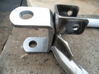
InspirationI've been inspired by that since seeing it on your steering bracketry, and I like it. Thought about it and concluded that since nearly all of my hardware came hand-picked right out of the shelf bins at H.D., it's understandable how I ended up double-nutting everything against vibration. Better pre-production planning on next build will allow me to go with the nylocks instead of the P-in-the-A of double-nutting.
Have grown a fondness for Zorotools.com, have gotten bulk .75" nuts (gr. 5), .75" axle nuts, and some odd stuff from them. Thinking an early order of about twice as many nylocks as I plan for would make that next build so much better, thanx for the inspiration, will save me some perspiration.
")
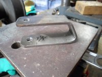
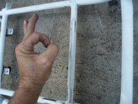
...that's what's it's ALL about

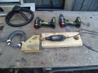
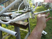
But...um...your prolly gonna need more than that

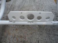
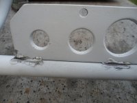
...'cause they go quick (notice the empty 5/16" slot in that "tray")
I'd buy 'em by the pound(s)

...ya gotta think of them "next" project(s) toooooo


 Bansil
