Karts of Kaos
the many mowers guy
sounds like a cool build
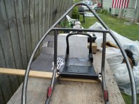
It's not just a reverse trikeWell, curiosity has now gotten me a look at a Polaris Slingshot. Cool, a 4-cylinder 5-speed reverse trike. That would be exhilarating and terrifying at the same time, at least with someone like me on the throttle. What are you going to power your mini version with?
")


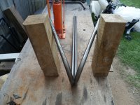
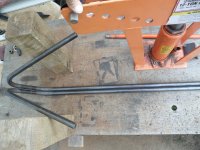

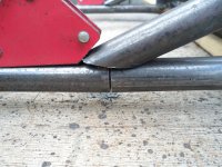
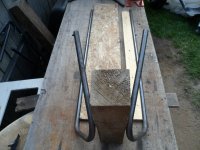
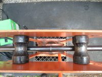
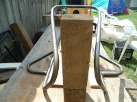
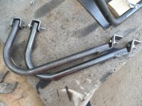
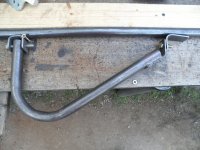
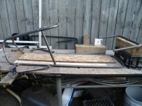
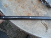
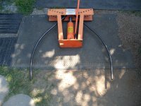
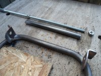
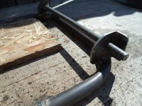
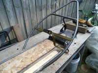
I use regular old 1/2" schedule 40 water pipeWhat is the wall thickness 9f your tubing?
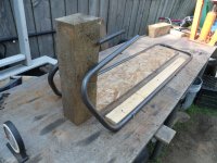
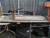
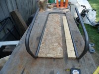
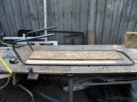
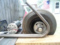
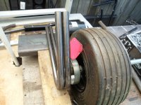
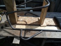
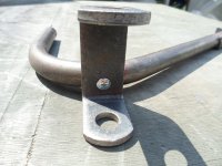
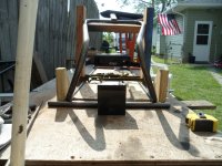
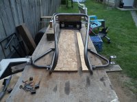
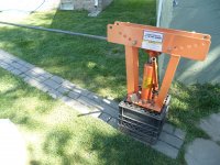
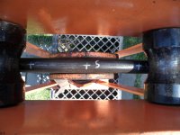
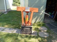
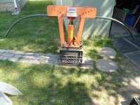
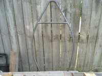
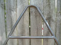
Can you show a picture of your bending method.
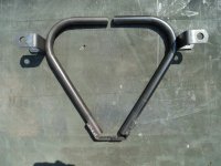
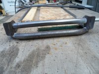
I'm impressed with the tight radius you are getting. Makes it all look very professional.

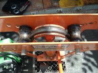

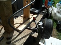


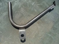
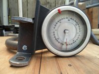
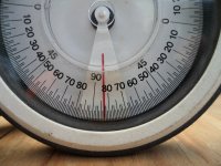


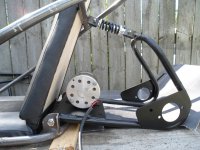
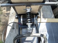
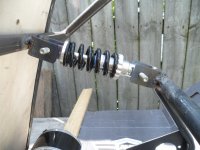
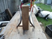
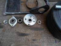
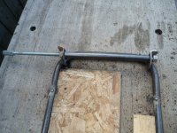
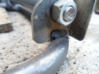
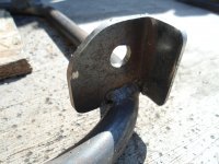
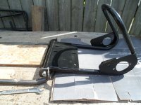
Yup, an adjustable castor bolt could be installedYou said you're going to weld the caster angle in, but I wonder..............Wouldn't this be a good opportunity to make a caster swivel more permanent (than the screw) and weld in an adjuster bolt for later adjustments? You're already in the adjustable phase of what could become a permanent and possibly useful attachment. I have no science to base this on, but just have a feeling that the trike even in the reverse configuration would lend itself to a slightly different set of adjustments for caster, camber, toe, etc. than a common 4-wheel configuration.


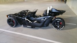
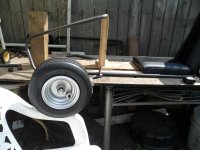
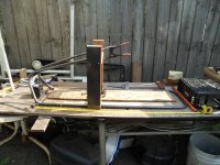
Um...go cart size LOLBlew by at 45 mph, but caught a look at a real Slingshot this morning outside the old Yamaha shop, gloss black with some neon green accents, very wicked looking. They're a little longer and bigger than I had thought, pretty hefty piece of machinery, what % scale would you guess you're building?