Sequoia Electrathon Racer

Functional Artist

Well-known member
Messages
4,428
Reaction score
1,719
Location
Toledo, Ohio
Here bees sum pickters frum wen we jus starded.

View attachment 145930 View attachment 145931

Maybe ya can git bedder idea, of what it is.
Hey T,
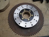
I used the same kinda concept (bolted a rotor to the hub of a sprocket) on my mini-Aerial Atom kart
SAM_1600 (1).JPG
Another view
SAM_1602 (1).JPG
But, for this situation the rotor flange (wood in the middle) needs to be permanently welded on to the hub
...& then, mount the rotor on to the outer side of the flange
...& the sprocket to the inner side of the flange

So, back to the wooden mock up hub
...maybe something like this
SAM_1609 (1).JPG
On the wheel
SAM_1611 (1).JPG
Side view
SAM_1613 (1).JPG
A closer view
SAM_1612 (1).JPG
I was thinking that by using a mostly blank sprocket, that maybe we can use the (6) rotor bolts
SAM_1619 (1).JPG
...to also, mount a DIY split sprocket (with (3) bolts on each side of the split)
* This sprocket is only for illustration purposes ('cause the center hole is too big)
SAM_1621 (1).JPG
 

Attachments

  • SAM_1608 (1).JPG
    SAM_1608 (1).JPG
    3 MB · Views: 1

Functional Artist

Well-known member
Messages
4,428
Reaction score
1,719
Location
Toledo, Ohio
There is a lot going on there and the spindle should be supported at both ends. A spindle supported on one end is possible with enough gussets extending outboard of the swing arm, and a strong enough spindle.
Hey T,
I started off contemplating just using a (longer (6") version) of a standard go kart spindle, like we are using on the front
...just have to mount it to a swing arm
...& make it stationary (so it can't turn, anymore)

Like one of these (6" x 5/8") spindles
https://www.bmikarts.com/Complete-Spindle-Set--6-x-58_p_2946.html
...or maybe just use a (well supported) ~6" 5/8 bolt on a custom swing arm

* I like your solution for the safety pins on the front hubs
...but, them (6" spindles) may also be an option for use on the front ;)

More info as to weight and horsepwer needed.
The weight of the racer should (hopefully) be ~150 lbs.
...& driver ~150 lbs.
...plus, ~30 lbs. of ballast (if entered in an EA sanctioned race)
...so, probably/hopefully in the 300 lbs. - 350 lbs. range :thumbsup:

A 48V 1,000W MY 1020 motor is rated at ~1.2HP
...or a 60V 2,000W MY-1020 brushless motor is rated at ~2.75HP :2guns:
 

Master Hack

Well-known member
Messages
2,038
Reaction score
3,266
Location
Mountain top Labratory
1. Why does the hub have to be welded? Rules?
2. the sprocket doesnt need to be through bolted to the rotor. Get some material with an OD big enough to use that sprocket. It can have different hole patterns on each side with threaded holes. the single point mount for the rear axle would work if ya use about a 8" SHCS. That way ya can build a 3" support on the awing arm.
weight and HP are less than l expected.

3. what is the point of 6 " spindles on the front?
 

Functional Artist

Well-known member
Messages
4,428
Reaction score
1,719
Location
Toledo, Ohio
1. Why does the hub have to be welded? Rules?
2. the sprocket doesnt need to be through bolted to the rotor. Get some material with an OD big enough to use that sprocket. It can have different hole patterns on each side with threaded holes. the single point mount for the rear axle would work if ya use about a 8" SHCS. That way ya can build a 3" support on the awing arm.
weight and HP are less than l expected.

3. what is the point of 6 " spindles on the front?
1. Just thought that welding the flanges to the hub "was" the plan

2. Just thought that "if" a sprocket was being custom drilled, it would be simpler (& dual purpose) to use (1) set of bolts for mounting both components

3. Just saying that it would have been another potential solution, to the safety pin clearance issue
 

Master Hack

Well-known member
Messages
2,038
Reaction score
3,266
Location
Mountain top Labratory
That driven sprocket that you salvaged off the Titanic will clean up nicely with a dip in muratic acid.
But what a goofy hole pattern...
Just another option.
 

Functional Artist

Well-known member
Messages
4,428
Reaction score
1,719
Location
Toledo, Ohio
That driven sprocket that you salvaged off the Titanic will clean up nicely with a dip in muratic acid.
But what a goofy hole pattern...
Just another option.
Hey T,

Yup, I agree
...but, that sprocket is off of/for use with a Peerless differential from a Simplicity riding lawn mower
...is for use with #40 (pitch) chain
...& it has 68T (teeth)

We will be using #35 chain
...& something like ~50T
* Something like this
https://www.bmikarts.com/Azusa-Aluminum-Sprocket-35-Chain--4-Bolt-Circle_p_4017.html

FYI: The motor will have a 10T drive sprocket
...& the wheels have a 50T driven sprocket
...for a 5:1 GR (gear ratio)
&
The wheels I'm using have a circumference of ~51"

So, using the
Ballpark Equation
MS/GR=ASxTC=IM/FT=FMxHR=FHxMM= MPH

Motor Speed/Gear Ratio=Axle Speed x Tire Circumference = Inches per Minute traveled/Foot(12) = Feet per Minute traveled x Hour(60) = Feet per Hour traveled x MPH Multiplier(.000189) = Miles Per Hour


If the motor does ~3,000 RPM's
...& were running (for this example) a 5:1 gear ratio
...& the golf cart wheels have a ~51" cir.

Then, the math would look like:
3,000/5 = 600 (axle speed)
600 x 51 = 30,000 (inches per min traveled)
30,600/12 = 2,550 (feet per min traveled)
2,550 x 60 = 153,000 (feet per hour traveled)
153,000 x .000189 = 28.92 MPH :2guns:
BTW wood does not weld very well... :rolleyes:
But, it works GREAT for making quick mock-ups :thumbsup:
 

Functional Artist

Well-known member
Messages
4,428
Reaction score
1,719
Location
Toledo, Ohio
Ima ordered some stuff
...so, whilst wesa waitin'we'll get back to the chassis for a minute :thumbsup:

Recently (durin' the cold spell) I took an online "crash course" in aerodynamics, at the Univ. of YouTube :innocent:
...& after some edumication, I came to the conclusion that "the more ya know, the less ya wanna know"

Because it became pretty clear that my big 'ol slopin' windshield
...& "fancy" curved "bighead lookin' roofline had a massive amount of "frontal area"
SAM_1531 (1).JPG
Frontal view
SAM_1534 (1).JPG
Like, ~32" vertically
SAM_1537 (1).JPG
...& ~15" horizontally
SAM_1535 (1).JPG
...& that adds up to......Um...well...a...lot of surface area or "wetted area" (technical term)
...for the wind to be able to inflict resistance or "drag" upon :huh:

So, after a script re-write
...& some re-calculation-s
Wesa goin'/went topless :bannana:
SAM_1559 (1).JPG
I even aerodynamicized (new word) :p the "nose"

Here is an after "down sized" frontal view
SAM_1560 (1).JPG
 

ezcome-ezgo

G'me sumthin to write on
Messages
4,804
Reaction score
1,379
Location
Atlanta, GA
"Frontal area" is often unavoidable as you must have room for yourself and sufficient structure around you to keep you safe. If you wanted to pursue minimal "frontal area", you should design it so that you lay completely flat and all structure and working mechanisms are either in front of or behind you. As you can see below, it is less than ideal. Aerodynamics is a constant compromise.

1709061848584.png
 

Denny

Canned Monster
Messages
8,596
Reaction score
4,836
Location
Mayberry, Indiana
Under 30 mph aerodynamics play less of a role. The best way to improve without a wind tunnel it is tape 2” pieces of yarn every couple of inches apart and drive it. Have someone film it as you do and and replay the film to see where the yarn is swirling and change the shape of the body there. Lift and downforce are also areas of concern as they too will induce drag.
 

Master Hack

Well-known member
Messages
2,038
Reaction score
3,266
Location
Mountain top Labratory
Egor said he’s gunna drill the wheel flanges tomorrow. He wants me to confrim
ya want it threaded 1/2 x 20? Left hand as per the drawing? :ROFLMAO:
l’m not confirming anything, THAT has to come from the chief engineer.
 

Functional Artist

Well-known member
Messages
4,428
Reaction score
1,719
Location
Toledo, Ohio
"Frontal area" is often unavoidable as you must have room for yourself and sufficient structure around you to keep you safe. If you wanted to pursue minimal "frontal area", you should design it so that you lay completely flat and all structure and working mechanisms are either in front of or behind you. As you can see below, it is less than ideal. Aerodynamics is a constant compromise.

View attachment 145991
Hey EZ,

Yup, I agree ;)
...& Ima not a big fan of laying down to drive
...so, Ima goin' for a "happy medium"

My thinkin' was that a drivers head/helmet
...& a roll bar (or 2) should have much less "frontal area" than the big 'ol windshield/roof that we had :thumbsup:
 

Functional Artist

Well-known member
Messages
4,428
Reaction score
1,719
Location
Toledo, Ohio
Don't the rules call for a "roll bar" of some sort?
Hey T,

Yup, here is an excerpt from the rulebook:

4 ROLL BAR
1. The roll bar must protect the driver's head/helmet in the event of a roll-over. It must be tall and wide enough to do this considering the full range of possible movement.
2. The roll bar structure must be triangulated with at least three legs or panel equivalent. Triangulated bracing can be either forward or rearward.With three legs bracing must extend from the top of the roll bar and securely attach to the vehicle structure, with four legs, each of the braces must extend to within 4" of the top. Any roll bar that is constructed from more than one continuous piece must be reinforced and braced triangularly from all junctions/joints in addition to the top.
3. The roll bar structure must appear to be sturdy enough to withstand the vehicle being dropped, upside down, from an altitude of one foot, with the driver inside without failure.
4. The driver’s helmet must be below a straight line drawn from the top of the roll bar to the top of the highest structural point when the driver is securely belted in driving position. (see drawing).
5. Composite or monocoque vehicles with integral rollover protection must meet comparable strength and clearance requirements.

(page 6.)

So, we'll incorporate some kinda head protection :cheers2:
I got some ideas :idea2:
 

Master Hack

Well-known member
Messages
2,038
Reaction score
3,266
Location
Mountain top Labratory
Started setting up to make wheel flanges. Egor looked at the drawings and came back with the tooling.
Didn't find that 1/2 x 20 LH tap, But did find a 1/2 x 13 LH! Want to substitute?
WTF?? There was that box full of random taps I bought at that swap meet a coupla years ago...

IMG_4005.JPG
 

Functional Artist

Well-known member
Messages
4,428
Reaction score
1,719
Location
Toledo, Ohio
Started setting up to make wheel flanges. Egor looked at the drawings and came back with the tooling.
Didn't find that 1/2 x 20 LH tap, But did find a 1/2 x 13 LH! Want to substitute?
WTF?? There was that box full of random taps I bought at that swap meet a coupla years ago...

View attachment 146017

Hey T,
I have a bunch of these, standard golf cart/boat trailer 1/2" x 20 wheel bolts :thumbsup:
Seachoice Marine Spare Wheel Bolt-1/2 X20 (5) Scp 53901

https://www.ebay.com/itm/2612470945...1622290073&itmmeta=01HQRQ8MS1S54DKPASJN6XJBVM

Think they'll be adequate for this project? :unsure:
 
Top