Sequoia Electrathon Racer

Master Hack

Well-known member
Messages
2,038
Reaction score
3,266
Location
Mountain top Labratory
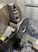
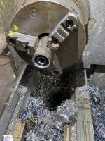
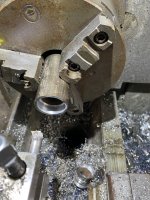
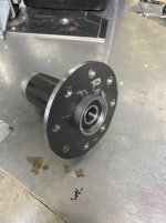
I think Egor negotiated some kinda deal when he took the company truck on that national sales tour. I dunno know, every time l ask, a get some BS about special projects, skunkworks and some anti gravity machine. I just let him go, sales are up, way up.
 

Master Hack

Well-known member
Messages
2,038
Reaction score
3,266
Location
Mountain top Labratory
Are the bearings going to be flush, with the edge of the hub?
...& how's the clearance, with the Caliper bracket, installed?


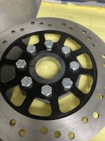
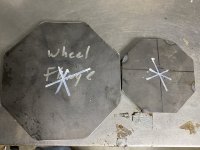
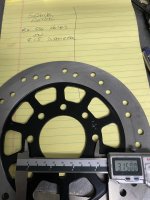
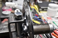
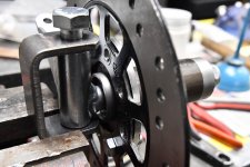
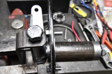
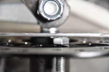
No not yet. I'm not sure what ya have in mind here. Even with the bearings flush with the end there isn't enough clearance to the bolt heads. we need to work on the solution for that. how much space do ya need between the rotor and bracket? I can turn down hex bolt heads, but SHCS or button heads. Spacers?

E58A0D0B-B668-425A-831D-F59BE3574088_1_105_c.jpegView attachment 145677
 

Functional Artist

Well-known member
Messages
4,428
Reaction score
1,719
Location
Toledo, Ohio
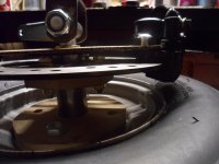
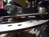
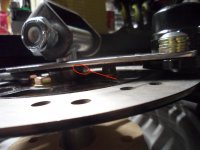
The rotor bolt clearance seemed OK when doing the original CAD mock up
SAM_1370 (1).JPG
...& then, when trying the steel bracket too
SAM_1408 (1).JPG
But, I may have neglected to mention, that I figured in the use of a washer (AKA shim) :unsure:
...in between, the bracket & hub to
1.) to "space" the bearing away from the Caliper bracket a bit
2.) the thickness of the washer may/could be used to help "fine tune" the centering of the Rotor, in between the brake pads

I think you suggested using Buttonhead bolts
...which may add a bit extra clearance :thumbsup:
 

Master Hack

Well-known member
Messages
2,038
Reaction score
3,266
Location
Mountain top Labratory
What am I see'n here? looks like the bearing is sticking out?
Keep in mind this is just a rough mock up. The bearings are about .100 recessed in the end of the hub. I was weighing the options. I can gain some there and button head will help. What is the washer thickness?
Stay tuned, adjustments to follow.

Image.jpg
 

Functional Artist

Well-known member
Messages
4,428
Reaction score
1,719
Location
Toledo, Ohio
Yup, good eye! ;)
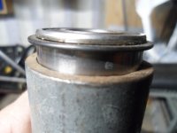
...that is one of them bearings with the snap ring

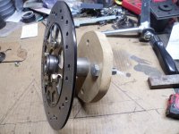
Wooden/steel mock up hub
SAM_1417 (1).JPG
The washer/spacer was to help "make up" for this :thumbsup:

A closer view
SAM_1346 (1).JPG
 

Master Hack

Well-known member
Messages
2,038
Reaction score
3,266
Location
Mountain top Labratory
Ok. That makes all the difference.
is that what ya plan to use? thats about .125 or so and another .100 at the current bearing location. But if ya based yer drawing off of that bearing location, we still be about .125 off with thebearing flush with the end. (All dimensions are based on poor memory and guesswork, and may not resemble actual dimensions in any way. Cuz i'm too lazy to walk back up to the Mountain top lab. Your results may vary)
 

Master Hack

Well-known member
Messages
2,038
Reaction score
3,266
Location
Mountain top Labratory
Yer drawing calls for hubs 4"OAL. How do the sticky outy bearings figger in that?
is it 4 " including the sticky outy things or 4 " plus the sticky outy thing?
l believe therein lies the problem.
 

Master Hack

Well-known member
Messages
2,038
Reaction score
3,266
Location
Mountain top Labratory
Makes sense now. My mistake. I thought we had ditched the idea of using snap ring bearings. So l be thinkin the overall length of the hub more than 4? OR the .437" inset of the flange is measured from the end of the tube, without compensation for the sticky outy part of the bearing??
 

Functional Artist

Well-known member
Messages
4,428
Reaction score
1,719
Location
Toledo, Ohio
Hey T,

The steel tube on the mock up hub was 3 3/4" long
...& the bearings "stuck out" ~1/8" on each end

When I listed the measurements in the drawing, I compensated for the bearings (with snap rings) "sticking out" (~1/8") on each end
...by designating the hub tube to be 4" 😉

So, the hub (tube) is 4" overall
...with the bearings recessed (inside of the tube)
...& flush with the end, of the hub, on each end

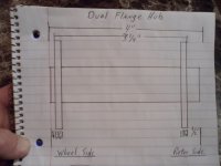
The flanges need to be 3 1/4" (outer edge to outer edge)
...& the rotor side flange needs to be 1/2" from the end of the hub
...the wheel side flange to the end of the hub distance isn't really that important

The main thing is that there is still enough of the spindle shaft, protruding from the end of the hub, for a Castle nut & Safety pin
...a 4" hub, on a 4 1/2" spindle :thumbsup:
SAM_1427 (1).JPG
Sorry, I guess I should have also illustrated the bearings & their positioning, in the drawing (my bad) :surrender:
 
Top