Polaris

Functional Artist

Well-known member
Messages
5,654
Reaction score
3,293
Location
Toledo, Ohio
I didn't do a video while building the 14S 48V 15AH battery pack for Polaris
...but, I took some pics :thumbsup:

First cell stuck thru the holder, with the tabs bent over
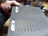
SAM_0981.JPG
I used basically the same procedures, as when I built a similar 14S 48V 15AH battery, pack last year ;)

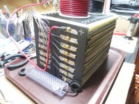
* I added individual "leads" to each of the cell connections, to be able to connect a cell monitor :sifone:
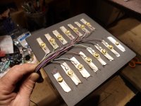
SAM_0983.JPG
 

Functional Artist

Well-known member
Messages
5,654
Reaction score
3,293
Location
Toledo, Ohio
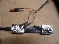
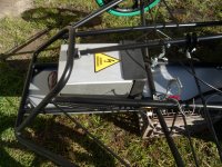
I'm going to mount the shunt (a measuring device that mounts inline with the Negative battery cable & sends info to the PZEM-051 power meter, up on the dash) 🤓
SAM_1005.JPG
Right in front of the battery, inside of the battery box (should be a good-n-safe spot) ;)
SAM_1004.JPG
To keep it insulated ...from ...well...everything (battery connections, terminals, steel box etc.)
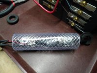
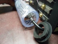
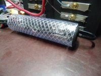
...the shunt will reside inside of a piece of vinyl tube
Like this
SAM_1009.JPG
...& have a couple of modified rubber grommets, on each end to help seal 'em' up & look a bit more professional :thumbsup:
SAM_1010.JPG
Kinda like this :cheers2:
SAM_1011.JPG
 

Denny

Canned Monster
Messages
11,973
Reaction score
8,479
Location
Mayberry, Indiana
I'm going to mount the shunt (a measuring device that mounts inline with the Negative battery cable & sends info to the PZEM-051 power meter, up on the dash) 🤓
View attachment 143195

Right in front of the battery, inside of the battery box (should be a good-n-safe spot) ;)
View attachment 143194
To keep it insulated ...from ...well...everything (battery connections, terminals, steel box etc.)
...the shunt will reside inside of a piece of vinyl tube
Like this
View attachment 143196
...& have a couple of modified rubber grommets, on each end to help seal 'em' up & look a bit more professional :thumbsup:
View attachment 143197
Kinda like this :cheers2:
View attachment 143198
Plus it helps keep the fire more centralized and located in one spot.
:roflol: :sifone:

Hell’o Kevin you know I like you buddy! I only kid you because I like and respect you!
Denny
 
Last edited:

Functional Artist

Well-known member
Messages
5,654
Reaction score
3,293
Location
Toledo, Ohio
Plus it helps keep the fire more centralized and located in one spot.
:roflol: :sifone:

Hell’o Kevin you know I like you buddy! I only kid you because I like and respect you!
Denny
Hey Denny,
No worries, pal :cheers2:

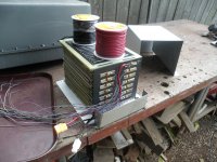
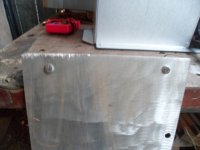
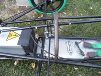
Next, I made up a "tray" or bottom for the battery box
SAM_1014.JPG
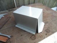
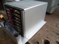
Battery box assembled
SAM_1015.JPG
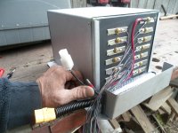
* Notice there are (3) separate groups of wires coming out of the battery box
1. The connections for the shunt (upper)
2. Charge/discharge connector/battery cables (middle)
3. BMS (Battery Monitoring System) wiring harness (lower)
SAM_1016.JPG
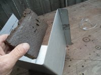
* Tip: An old sanding sponge easily rounds & smooths the sharp edges of sheet metal ;)
SAM_1012.JPG
 

Functional Artist

Well-known member
Messages
5,654
Reaction score
3,293
Location
Toledo, Ohio
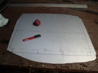
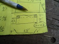
Battery box cover
Rough idea/notes 🤓
SAM_1020.JPG
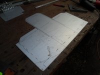
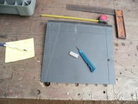
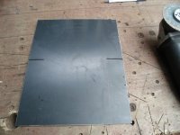
Piece of plastic (easily scribed & cut with this "little guy")
SAM_1019.JPG
Used the cut off wheel for these little/short cuts

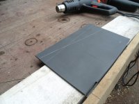
* Notice the bend lines? (marked on the inside of the piece)
SAM_1023.JPG
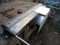
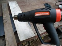
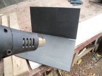
Set up a heating station :)
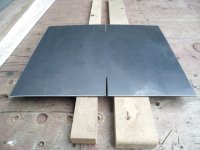
...& placed the piece of plastic on 2 boards spaced ~1" apart
SAM_1025.JPG
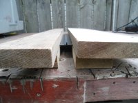
...then, placed 2 boards on top of the plastic (also, spaced ~1" apart)
SAM_1027.JPG
** The bottom boards are to "space" the piece of plastic, above the workbench
...so, the heat can easily "pass thru" (the piece)

The upper boards helps to protect the areas of plastic that we don't want heated
...& also, helps concentrate the heat, in just in the area, that we want heated ;)
SAM_1028.JPG
Ugggg, I bent it backwards :huh::furious2::mad2:
SAM_1029.JPG
Re-heat
...& re-bend
Ok that's better
SAM_1030.JPGAdded a couple more bends
SAM_1031.JPG
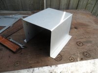
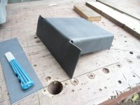
After a little bit of trimmin' :thumbsup:
SAM_1033.JPG
 

Functional Artist

Well-known member
Messages
5,654
Reaction score
3,293
Location
Toledo, Ohio
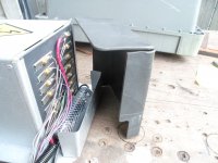
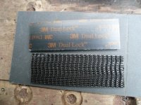
Industrial Velcro :thumbsup:
SAM_1034.JPG
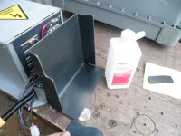
Clean/de-grease, the (2) areas
SAM_1038.JPG
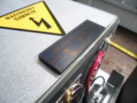
* Installation tip:
First, join the (2) pieces of Velcro together
...then, peal back the protective cover
...& stick/mount the (2) joined pieces, where they should be ;)
SAM_1039 (1).JPG
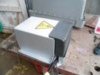
Then, peal the other protective cover off
...& simply align & mount the adjoining piece, where it should be :cool:
SAM_1040 (1).JPG
 

Functional Artist

Well-known member
Messages
5,654
Reaction score
3,293
Location
Toledo, Ohio
The (4) 12V 20AH SLA's have been removed :wai:
SAM_1042 (1).JPG
When removing the Belly Pan, I noticed that it & the bolts have "taken a couple of hits" :ack2:
SAM_1043 (1).JPG
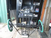
I took this opportunity to weigh the chassis 🤓
Just stood it up on a bathroom scale ;)
SAM_1051 (1).JPG
Looks like the entire kart (without batteries) weighs just a bit over 100 lbs. :thumbsup:
SAM_1050 (1).JPG
 

Functional Artist

Well-known member
Messages
5,654
Reaction score
3,293
Location
Toledo, Ohio
Looks like yer gonna beat your previous estimated GVWR by a bunch!
Hey T,
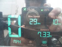
I'ma thinkin' the whole package should Gross Out, just over 300 lbs. :thumbsup: (He...he...I said Gross Out) :ROFLMAO:

Chassis ~100 lbs.
Batt pack ~ 30 lbs.
Driver ~150 lbs.
Ballast ~30 lbs.

* I didn't "do the math" before hand
...& was kinda surprised, when the top speed jumped all of the way up to 29 MPH :sifone:
SAM_1099 (1).JPG
 

Functional Artist

Well-known member
Messages
5,654
Reaction score
3,293
Location
Toledo, Ohio
Did anyone notice the front wheel goin' all wonky (ex: ~10:55) a couple of times, in the last video? :unsure:

Upon further examination, it seems/looks like the steering shaft is flexing (up to ~1/2") in the middle :furious2:

So, I may have to add a center support
...but, for now, I just stiffened 'er up ;)
...& we'll see how that goes :thumbsup:
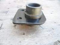
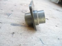
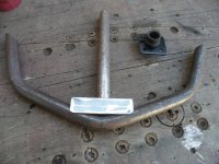
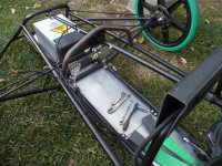
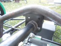
I've been workin' on a center support for the steering shaft :popcorn:
SAM_1169.JPG
Side view
SAM_1170.JPG
Profile
SAM_1171.JPG
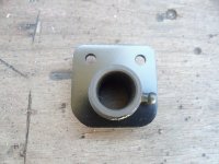
Mounting bracket
SAM_1172.JPG
Dry fit
SAM_1174.JPG
Profile
SAM_1175.JPG
Up close
SAM_1176.JPG
* Adding a bearing or bushing in the middle of a shaft, isn't the easiest thing to do
...because, "if" the bearing isn't pretty well centered, on the shaft (in between the other (2) bearings) there will be binding :ack2:

Especially if welding the bearing holder "in place"
...because when welding, it "draws" the (2) pieces of metal together a little bit
...& again, "if" the bearing isn't pretty well centered, on the shaft there will be binding :furious2:

So, my plan is to weld the bearing support bar, on to the chassis 🤓
...& then, bolt the bushing holder, to the support bar ;)
 
Top