Hell-raiser 72V Electric Racing Kart

Functional Artist

Well-known member
Messages
4,411
Reaction score
1,694
Location
Toledo, Ohio
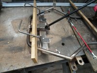
I do get the spec of F.5.12.7 for the bolts on a sleeved joint. What I don't get is why do all of that work of drilling many holes to bolt it together when there doesn't seem to be any spec that says you can't just weld it.
Just drill 2 holes thru 1 side only of each of the outer tubes for inspectors to see how far the insert goes. Bolt specs call for 16 aligned holes.
Yup, I'd say it could have been welded :thumbsup:

I just figured this would be a good way ta explain the specifics, of a Sleeved Butt Joint ;)
...show where it may be used :cheers2:
...& also, an example of one, in use :sifone:
 

Functional Artist

Well-known member
Messages
4,411
Reaction score
1,694
Location
Toledo, Ohio
Steering Bushings
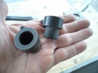
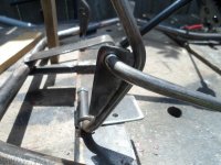
The bushings I'm using on this steering shaft, are actually re-purposed front wheel bushings off of a MTD Yard Machine riding mower.

Their made out of some kind of tough plastic
...for use with/on a 5/8" shaft
...have a nice wide/thick rim
...& even have a grease-able fitting molded in

SAM_4243.JPG
They can be mounted in a piece of tube welded in place or just in a simple hole
...will provide us with some nice-n-smooth "steering action"
...&/also, will eliminate that annoying metal to metal squeak many go karts "classically" have
SAM_4246.JPG
 

madprofessor

"Loose Cannon Creations"
Messages
2,899
Reaction score
888
Location
Jacksonville, Florida
Very unique bushings, never seen that kind of angled zerk fittings before. BTW: While the extra work is more than I would be willing to attempt, the steering setup I saw here before (don't remember who did it) that would come apart completely so shaft and all could be easily R&R'd was the coolest ever. Slap-on double-split locking collars made it completely adjustable and easy as pie, without a bunch of hole drilling, was just a very cool kind of home engineering.
EDIT: Just found that steering setup, it was done by SquidBonez on his Big Block Mini-Buggy...................(19) Full Suspension Big Block Mini-Buggy Build | Page 6 | DIY Go Karts
 
Last edited:

Functional Artist

Well-known member
Messages
4,411
Reaction score
1,694
Location
Toledo, Ohio
Now, with the steering shaft mounted
...& the spindle mounts welded on

Next on the agenda would be tie rod ends
...but, first let's check on the "Ackerman"

Ackermann
"Ackermann steering geometry is a geometric arrangement of linkages in the steering of a car or other vehicle designed to solve the problem of wheels on the inside and outside of a turn needing to trace out circles of different radii.

It was invented by the German carriage builder Georg Lankensperger in Munich in 1817, then patented by his agent in England, Rudolph Ackermann (1764–1834) in 1818 for horse-drawn carriages.

The intention of Ackermann geometry is to avoid the need for tyres to slip sideways when following the path around a curve.

A simple approximation to perfect Ackermann steering geometry may be generated by moving the steering pivot points inward so as to lie on a line drawn between the steering kingpins and the centre of the rear axle. The steering pivot points are joined by a rigid bar called the tie rod which can also be part of the steering mechanism, in the form of a rack and pinion for instance. With perfect Ackermann, at any angle of steering, the centre point of all of the circles traced by all wheels will lie at a common point. Note that this may be difficult to arrange in practice with simple linkages, and designers are advised to draw or analyse their steering systems over the full range of steering angles.


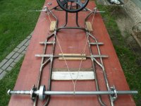
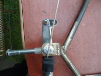
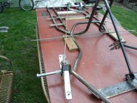
Marked the center point of the rear axle
...& tied (2) pieces of string at/around that point (on the axle)
...then, ran 'em up to/across the spindle bolts (up front)

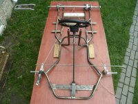
A view from the "bow"

SAM_4247.JPG

Another view (from the "stern")
SAM_4249.JPG
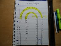
According to "The Ackerman Jig", it looks like the "pivot point" (where the tie rod end connects) needs ta be moved "inwards" ~1"
SAM_4251.JPG
 

Functional Artist

Well-known member
Messages
4,411
Reaction score
1,694
Location
Toledo, Ohio
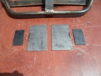
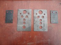
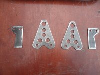
I used some 1/8" steel ta make a couple of "Ackerman adjustment brackets" (ta go on the spindles)
...& a couple of "dual pivot" pitman arms too (ta go on the steering shaft) ;)

Started off with some "blank slates"
SAM_4255.JPG
...then did some drillin'
SAM_4257.JPG
...& then, some shapin'
SAM_4258.JPG
* All done with simple (mostly Harbor Freight) hand tools (tape measure, scribe, a drill & a variety of bits & a grinder (rough & smooth)
...& some imagination:sifone:
 

madprofessor

"Loose Cannon Creations"
Messages
2,899
Reaction score
888
Location
Jacksonville, Florida
The spindle brackets are a good idea, looks like one bolt hole attaches to 90-degree spindle arm hole, and the other bolt hole attaches to tierods. Maybe the long length is to parallel the spindle arm and weld to it? Or drill another pair of holes to bolt it?
Pitman arm looks like it won't work as is, but you've almost got it. When spreading the tierod bolt holes apart to create Ackermann angle that way, the left tierod end does not go in the left side bolt hole, it reaches across and goes in the right side bolt hole. Vice versa for the other tierod end. Therefore the pitman arm bolt holes have to be shifted North/South enough for the tierods not to hit each other. Like maybe one of them North a 1/2", the other South a 1/2".
 

Functional Artist

Well-known member
Messages
4,411
Reaction score
1,694
Location
Toledo, Ohio
The spindle brackets are a good idea, looks like one bolt hole attaches to 90-degree spindle arm hole, and the other bolt hole attaches to tierods. Maybe the long length is to parallel the spindle arm and weld to it? Or drill another pair of holes to bolt it?
Yup
Pitman arm looks like it won't work as is, but you've almost got it. When spreading the tierod bolt holes apart to create Ackermann angle that way, the left tierod end does not go in the left side bolt hole, it reaches across and goes in the right side bolt hole. Vice versa for the other tierod end. Therefore the pitman arm bolt holes have to be shifted North/South enough for the tierods not to hit each other. Like maybe one of them North a 1/2", the other South a 1/2".

Have you read thru this "sticky" on Ackermann?
...& notice Sid reminds us Ackermann is spelled with (2) n's)
https://www.diygokarts.com/communit...ixes-diagrams-ackerman-angle-explained.23785/

AFAIU once the "Ackermann" is determined, for a specific vehicle then, ya can make the adjustment (either) @ the outer tie rod ends (on the spindles)
...(or) @ the inner tie rod ends (on the pitman arm)
...but, not both :cheers2:

I did this same concept on my Excalibur kart
...& it's the best handling kart I've ever driven ;)


Functional Artist

Well-known member
Messages
4,411
Reaction score
1,694
Location
Toledo, Ohio
Here is a "close up" pic of how it looks with the "Ackermann bracket" installed (lines up nicely) ;)
...just need to drill & add another bolt (to lock 'em together)
SAM_4260.JPG
...& a "step back" view
SAM_4261.JPG
 

madprofessor

"Loose Cannon Creations"
Messages
2,899
Reaction score
888
Location
Jacksonville, Florida
ya can make the adjustment (either) @ the outer tie rod ends (on the spindles)
...(or) @ the inner tie rod ends (on the pitman arm)
...but, not both :cheers2:
Sort of agree, why get confused by Ackermann adjustments on inner/outer ends both when one or the other will do, but some might need to use both. In the leading spindle arm setup like yours, a mistaken mismatch of tires to hubs might leave the inside of the front tires too far inward to allow spindle arm enough outward angle for proper Ackermann. Ran into that problem myself.
Then someone could pick up some spindle arm angle at that end of the tierods, and some more with a crossover of the tierods at the pitman arm.
 

Functional Artist

Well-known member
Messages
4,411
Reaction score
1,694
Location
Toledo, Ohio
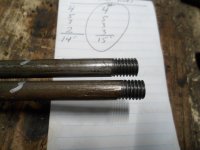
I "squared" the spindles & also, the steering shaft so, I could do some measurements, to make up the tie rods
...it required (2) 11" pieces of 5/16 rod with ~1 1/2" of "fine" threads cut onto each end)

When installing the tie rods, I adjusted 'em "toed in" just a bit :thumbsup:

Also, to help illustrate the Ackermann steering concept a bit more, I thought :idea2: maybe I can do some kind of a visual demo :cheers2:

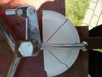
So, I cut a paper plate in half (just 'cause it was round & paper)
...& drew lines on it @ 45*, 90* & 135* (Angle Gauge)
...& then, "aligned" it under the spindle & stapled it down
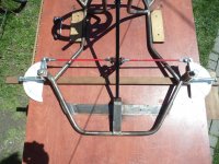
SAM_4268.JPG
A closer view of the "Angle Gauge"
SAM_4270.JPG
Next, I "traced" along both sides of the spindles @ ~90* & also, @ full turn, left & right (blue ink)

Here is the info, on the port (left) spindle:
....on a full left turn, it turns to ~3/8" above the 45* line
...& then, on a full right turn, it turns to ~7/8" below the 135* line

As can be seen, (on this port (left) spindle)
...when turning left, this "inside tire" turns at a sharper angle
...than, it does when turning right (when it would be the "outside tire")

So, this means that on a left turn, the left "inner" tire would "follow" a smaller circle, than the right "outer" tire
...& then on a right turn, the right "inner" tire would "follow" a smaller circle, than the left "outer" tire ;)

Pic of Angle Guage (with "turn" info) on the port (left) spindle
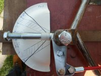
SAM_4278.JPG
 
Last edited:

Functional Artist

Well-known member
Messages
4,411
Reaction score
1,694
Location
Toledo, Ohio
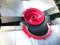
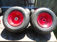
Rim painting tip
Before painting the rims, clean 'em up good (scuff off the gloss (if new) or corrosion (if used)
...& then, mount the tires
...but, don't air them up (yet) ;)

Next, "tuck in" some cardboard (with "half-moon" cut-outs) in-between the rim & tire
...& wipe 'em down, again with degreaser
...then, give 'em a good/nice coat of paint :cheers2:
SAM_4265.JPG
After their dry, remove the cardboard
...& then, air 'em up :thumbsup:
SAM_4276.JPG
 

Functional Artist

Well-known member
Messages
4,411
Reaction score
1,694
Location
Toledo, Ohio
Old playing cards or paper plates work great too. Masking tape stinks.
Yup, also, good tips :thumbsup:

The main point I was getting at (& totally forgot to even mention but, is probably pretty obvious)
...was by mounting the tires before painting, ya virtually eliminate the possibility of damaging your nice/new paint job, during mounting ;)
 

madprofessor

"Loose Cannon Creations"
Messages
2,899
Reaction score
888
Location
Jacksonville, Florida
Very kind of you to go to the trouble of clarifying Ackermann with doing the cutout 2D's and taking pictures, way more effective than all of the words I could stitch together.
Perhaps you would be willing to stretch a clearly visible line (clothesline, colored string, etc.) from rear axle center to well beyond the kingpins, with a spindle at 90-degrees, and another inline for Ackermann angle? A little more simplified. You're good at illustrating these concepts.
 

Functional Artist

Well-known member
Messages
4,411
Reaction score
1,694
Location
Toledo, Ohio
No problem, teamwork :cheers2:

stretch a clearly visible line (clothesline, colored string, etc.) from rear axle center to well beyond the kingpins, with a spindle at 90-degrees
I believe the 2nd pic in post #88 shows that :unsure:

I did a quick drawing to help "illustrate" ;) the concept, a bit more :thumbsup:

Check out my "crude" little Hellraiser :auto:

I added a "scale" along each side of the path, in 1/2" increments

Notice how both the left & right wheels travel the same distance while going straight
...but, when ya enter (in this example) a left turn, the (right) "outer" tire has to travel/follows a much larger circle
...than the left tire does
SAM_4283.JPG

* This drawing also illustrates why it's so difficult to turn, a kart, with a live axle
...'cause the "outer" tire has to travel a greater distance (thus turning more revolutions)
...& the "inner" tire doesn't have to travel as far (thus turning less revolutions)
...but, being on a solid/live axle, causes binding issues (tire rotation rates are fighting each other)

That's why when turning it's best for the kart to shift its weight a bit allowing the "inner" rear wheel to "lift up" slightly
...so, it kinda "skips/slips around the curve
...then, when ya straighten it out, the weight shifts back, so both rear tires get 100% traction, again 😎
 

Functional Artist

Well-known member
Messages
4,411
Reaction score
1,694
Location
Toledo, Ohio
Hey, where did ya get them tires?

Well, I'm glad you asked ;)

After the outrageous cost increase of the rims, I was looking for a "low cost solution" for some "racing slick" type tires
...& found these Carlisle Smooth Tread (slick) Tires at Surplus Center for ~$15.00 ea. (~$60.00 for all 4)
https://www.surpluscenter.com/Wheel...3x6-5-6-Carlisle-Smooth-Tread-Tire-1-5112.axd

13x6.5-6 Carlisle Smooth Tread Tire​

New, CARLISLE smooth tread turf tire. Model 5121861.Not for Highway Service. Often used on ZTR mowers & Made in the USA :thumbsup:

SPECIFICATIONS
  • Size 13x6.50-6
  • O.D. 12.9"
  • Tread Smooth
  • Mounted Width 5.9"
  • Rim Width 4.5"
  • Tubeless
  • Load Rating 480 lbs. @ 28 PSI
  • Ply Rating 4
  • Ply Material Nylon
  • Shpg. 6 lbs.
* On Amazon, these tires sell for over $30.00 ea.
https://www.amazon.com/Carlisle-512...eywords=carlisle+tires&qid=1652194779&sr=8-25

...& they cost even more, at most shops :unsure:

I'ma gonna see/test how well they hold up on our Hell-raiser :cheers2:
 

Functional Artist

Well-known member
Messages
4,411
Reaction score
1,694
Location
Toledo, Ohio
Racing kart style pedals

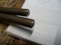
I cut (2) 15" pieces of 3/8" rod
...& rounded their tops
SAM_4288.JPG
...then, cut ~3/4" of course threads, into the other end
SAM_4286.JPG
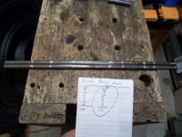
Next step was to mark 'em @ 4", 5" 3" & 3"
SAM_4285.JPG
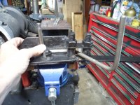
...& then, put 'em in the bender (I bent the (2) end bends first, keeping them "in line" then, did the middle bend
SAM_4292.JPG
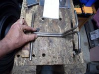
* They seemed to come out pretty even 😎
SAM_4293.JPG
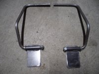
Fabricated some mounts
SAM_4297.JPG
Mounted 'em on the kart
SAM_4298.JPG
 

Functional Artist

Well-known member
Messages
4,411
Reaction score
1,694
Location
Toledo, Ohio
I added/welded on a "tab" I guess ya would call it (or maybe "flange") to each of the pedals
...where the "control rods" or cables will connect
SAM_4307.JPG
Then, made & installed a control rod for the brake system (3/8" rod connected to a 4 1/2" brake band) mounted on the port nacelle)
...with (2) "guides" (3" pieces of 3/8" tube) welded to the frame

* I had ta route it down under, the port batt pack
...then, have it "kick up" in the back, to align with the brake band
SAM_4312.JPG
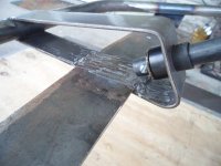
If ya look close, I included a "stop" (so, the brake pedal doesn't/can't "return" too far back, when released
...& a "striker" for a brake light switch
...&/also, a neat (IMO) control rod-to-brake band connector ;)
SAM_4315.JPG
 

Kartorbust

Well-known member
Messages
3,901
Reaction score
194
Location
Utica, NE
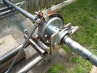
As long as they are locked down, the keys should hold the torque better across the whole axle, rather than say a 4 or 6 inch section. Less chances of the keys snapping and the key ways getting messed up.
 
Top