Hell-raiser 72V Electric Racing Kart

Functional Artist

Well-known member
Messages
5,640
Reaction score
3,274
Location
Toledo, Ohio
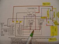
J1 Connector
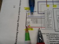
The signal LED's are connected thru the J1 connector

The green wire supplies the positive (+) to the green LED (thru J1 pin # 6 Green LED) (* didn't have a green pen)
...the red wire supplies the positive (+) to the red LED (thru J1 pin # 14 Red LED)
...the black wire supplies the negative (-) for both LED's (thru J1 pin # 7 RTN)
SAM_4470 (1).JPG
...& the white wire connects (J1 pin #3 Main RLY) to the contactor's coil negative (-)
SAM_4472 (1).JPG
J2 Connector
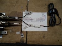
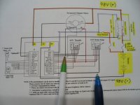
The throttles that I usually use, are the (3) wire (0 - 5V) Hall Effect thumb throttles (like used on scooters)

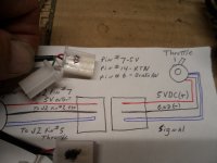
They require a 5VDC power supply, to power them thru J2 pin # 7 (5V Output) usually a red wire
...a negative (-) thru J2 pin #2 (RTN) usually a black wire
...& a signal wire that, when actuated, sends the throttle position to the controller thru J2 pin #5 (Throttle) (usually a green or white wire)
SAM_4462 (1).JPG
The brake "signal circuit" also, uses a (0 - 5V) thumb throttle.

They also, require a 5VDC power supply, to power them thru J2 pin # 7 (5V Output)
...a negative (-) thru J2 pin #14 (RTN)
...& when actuated, it sends a "signal" to the controller (thru pin #6 Brake AN) that the "brakes have been applied"
SAM_4466 (1).JPG
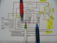
* Notice that the throttle, brake & thermistor all are supplied (5V) by J2 pin #7
SAM_4467 (1).JPG
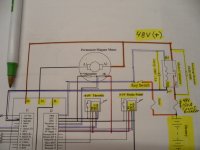
Here a quick view of where the negatives (-) for the signal components connect
SAM_4468 (1).JPG
...& also, where the "signal wires" for the different "signals" connect
SAM_4469 (1).JPG
Um...yea ;)
...kinda like that :innocent::devil2:
 
Last edited:

Functional Artist

Well-known member
Messages
5,640
Reaction score
3,274
Location
Toledo, Ohio
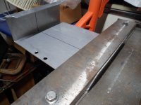
I cut a piece out of an old aluminum sign (~1/8" thick)
...& did some bendin' (ta shape it the way I wanted it)
SAM_4450.JPG
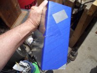
...then, some tapin' (ta designate the necessary cut-out & help protect the surrounding surface)
SAM_4451.JPG
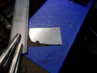
...then, some whittlin' (ta cut 'er out)
SAM_4454.JPG
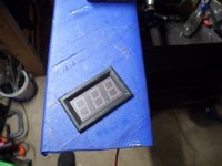
Yup, that should work ;)
...for a side mounted voltage indicator/meter (to indicate when/if & what voltage is present, at/in the control box) :thumbsup:
SAM_4455.JPG
 

Functional Artist

Well-known member
Messages
5,640
Reaction score
3,274
Location
Toledo, Ohio
"Hey...why you gonna have another meter? (& where ya gonna put it?)
I thought you said you was gonna use that fancy PZEM-051 meter up on the dashboard."
:huh:

Well, I'm glad you asked. :thumbsup:

Those (2) meters are (2) different components with (2) different functions.

The dash meter is for the driver.
It lets him know what's goin' on in & with the "tractive system" (EV.1.1 Tractive System – TS Every part electrically connected to the Motor(s) and/or Accumulator(s)

The voltage meter will be "side mounted"
...& is to alert/notify maintenance personnel, inspectors & even spectators that there "is" voltage present & what voltage :cheers2:

* The Formula SAE Rules 2022, that I've been using as a "best practices guide", require an:

EV.4.2 Energy Meter
EV.4.2.1 All Electric Vehicles must run with the Energy Meter provided by the organizer. Refer to the FSAEOnline Website AD.2.2 for detail information on the Energy Meter.
EV.4.2.2 The Energy Meter must be installed in an easily accessible location
EV.4.2.3 All power supplying the Tractive System must flow through the Energy Meter.
EV.4.2.4 Power and Voltage limits will be checked by the Energy Meter data. Energy is calculated as the time integrated value of the measured voltage multiplied by the measured current logged by the Energy Meter.


...& also, a

EV.6.7 Voltage Indicator
Each Accumulator Container must have a prominent indicator when High Voltage T.9.1.1 is present at the vehicle side of the AIRs
EV.6.7.1 The Voltage Indicator must always function, including when the Accumulator Container is disconnected or removed
EV.6.7.2 The voltage being present at the connectors must directly control the Voltage Indicator using hard wired electronics with no software control.
EV.6.7.3 The control signal which closes the AIRs must not control the Voltage Indicator
EV.6.7.4 The Voltage Indicator must: a. Be located where it is clearly visible when connecting/disconnecting the Accumulator Tractive System connections b. Be labeled “High Voltage Present"


So, Ima using the PZEM-051, as our "Energy Meter"
...& the digital voltage meter, as our "Voltage Indicator" ;)
 

Functional Artist

Well-known member
Messages
5,640
Reaction score
3,274
Location
Toledo, Ohio
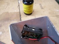
The piece of aluminum (from an old sign) wasn't actually painted, it just had a big sticker/decal "stuck" on it
...& after removing that old "decal", I noticed that, the surface was still pretty shinny

So, after removing the tape (that I used while cutting out for the meter) I thought I'd see if I could polish 'er up a bit more :thumbsup:

But, before that I did some research (at the Youtube school of DIY) :2guns:
...& found a video, of a guy that cleans the aluminum first, with a Scotch-Brite pad, soaked in WD-40
...then, polishes it up nice-n-shinny with some standard Aluminum Wheel Polish :drool5:

So, I scrubbed 'er down with some fine Scotch-Brite & WD-40 (as per the instructional video) :)
...& then, polished 'er up with some Aluminum polish (also, as per the video) :cheers2:

Um...not bad for a bent up piece, of an old sign ;)

* I could probably polish 'er up even better, with a bit more effort
...but, we got lots more ta do
...& I think it looks pretty kool 😎
...so, lets move on :auto:
SAM_4483 (1).JPG
 

Functional Artist

Well-known member
Messages
5,640
Reaction score
3,274
Location
Toledo, Ohio
I must confess, that the cut-out for the meter was a little "loose" (technical term)
...so, I "glued" 'er in with a couple of drops of Liquid Tape, on each corner ;)

* I also, kinda "glued" them little wires right onto the meter, ta make 'em a bit more sturdy :thumbsup:
SAM_4484 (1).JPG
 

Functional Artist

Well-known member
Messages
5,640
Reaction score
3,274
Location
Toledo, Ohio
When we were discussing the Voltage indicator, there were a couple of technical terms (for real this time)
...so, let's take a look at the FSAE Rules for 2022 (again) :cheers2:

EV - ELECTRIC VEHICLES
EV.1 DEFINITIONS
EV.1.1 Tractive System
– TS Every part electrically connected to the Motor(s) and/or Accumulator(s)

* The Tractive System is the entire electrical "drive line"

EV.1.2 Grounded Low Voltage - GLV Every electrical part that is not part of the Tractive System
* The GLV is all other electrical components (like meters & DC to DC convertors)

EV.1.3 Accumulator All the battery cells or super capacitors that store the electrical energy to be used by the Tractive System
* The Accumulator is the Battery pack

EV.3.2 Maintenance
EV.3.2.1 Safety glasses with side shields must be worn by all participating team members any time when:
a. Parts of the Tractive System are exposed while energized
b. Work is performed on the Accumulators
EV.3.2.2 Appropriate insulated tools must be used when working on the Accumulator or Tractive System

EV.4 ELECTRICAL LIMITATIONS
EV.4.1 Power and Voltage
EV.4.1.4
Supplying power to the motor to drive the vehicle in reverse is prohibited.

* Hmmm, no reverse is allowed

EV.4.2 Energy Meter
EV.4.2.1
All Electric Vehicles must run with the Energy Meter

* Yup, were gonna have an Energy Meter ;)

EV.5.2 Motor Controller The Tractive System Motor(s) must be connected to the Accumulator through a Motor Controller. No direct connections between Motor(s) and Accumulator.
* Yup, were gonna use a Kelly Controller :thumbsup:

EV.5.3.7 Each Accumulator Container must be labeled with the:
a. Symbol specified in ISO 7010-W012 (triangle with black lightning bolt on yellow background) with triangle side length of 100 mm minimum
b. Text “Always Energized”
c. Text “High Voltage” if the voltage meets T.9.1.1

* Ima gonna have ta get some of these stickers

EV.5.4 Grounded Low Voltage System
EV.5.4.1 The GLV System must be a Low Voltage system that is Grounded to the Chassis
EV.5.4.2 The GLV System must include a Master Switch, see EV.8.9.1

* The GLV System would be a low voltage system like a 12V circuit for lights & such

EV.5.9 Housings and Enclosures
EV.5.9.1 Every housing or enclosure containing parts of the Tractive System other than Motor housings, must be labeled with the:
a. Symbol specified in ISO 7010-W012 (triangle with black lightning bolt on yellow background)
b. Text “High Voltage” if the voltage meets T.9.1.1 EV.5.9.2 If the housing material is electrically conductive or possibly electrically conductive, it must have a low resistance connection to GLV System Ground, see EV.7.7

* Remember, were not actually going to have "High Voltage" since were only working with a 48V system

EV.6.2 Electrical Configuration
EV.6.2.1 All Tractive System components must be rated for the maximum Tractive System voltage
* This specifies that all wiring, switches & components "must" be rated for the maximum voltage that the system should ever have to "carry"

EV.6.2.4 Soldering electrical connections in the high current path is prohibited. Soldering wires to cells for the voltage monitoring input of the AMS is allowed, these wires are not part of the high current path.
* This specifies that all connections in the "high current" path "must" be "mechanical" connections & not soldered
** I'd say that's because soldered connections can "come loose" if the circuit becomes too hot

EV.6.4 Accumulator Isolation Relays - AIR
* AIR is a (technical term) for a contactor
** A contactor is a big "beefy" switch that contacts &/or isolates the Accumulator/Battery Pack from the Tractive System
...& is actuated/controlled by a smaller "signal" switch

EV.6.4.1 Every Accumulator Container must contain minimum one fuse (EV.7.6) and two or more Accumulator Isolation Relays (AIR)
EV.6.4.2 The Accumulator Isolation Relays must:
a. Be a Normally Open type

EV.6.5 High Voltage Disconnect - HVD A High Voltage Disconnect (HVD) must be included to quickly disconnect one or both poles of the Accumulator

* Were using a 48V 150A circuit breaker as our HVD

EV.6.6 Precharge and Discharge Circuits
EV.6.6.1
The Accumulator must contain a Precharge Circuit. The Precharge Circuit must:
a. Be able to charge the Intermediate Circuit to minimum 90% of the Accumulator voltage before closing the second AIR

* Yup, were gonna have a pre-charge circuit to protect the capacitators in the controller from a huge "inrush" of current upon start-up

EV.6.6.3 The Tractive System must contain a Discharge Circuit. The Discharge Circuit must be:
a. Wired in a way that it is always active when the Shutdown Circuit is open
b. Able to discharge the Intermediate Circuit capacitors if the HVD has been opened
c. Not be fused
d. Designed to handle the maximum discharge current for minimum 15 seconds

* We don't (currently) have a discharge circuit
...but, IMO it's something we should probably to look into

EV.6.9 Tractive System Active Light - TSAL
EV.6.9.1 The vehicle must include a Tractive Systems Active Light (TSAL) that must:
a. Illuminate when the GLV System is energized to indicate the status of the Tractive System

* The TSAL (when lit) is to indicate that the System is "live"

EV.8.3 Accumulator Management System - AMS
EV.8.3.1 An Accumulator Management System must monitor the Accumulator(s) Voltage
* The AMS is another (technical term) for a BMS (Battery Management System)

EV.8.10 Shutdown Buttons
EV.8.10.1
Three Shutdown Buttons must be installed on the vehicle.
EV.8.10.2 Each Shutdown Button must be a push-pull or push-rotate emergency switch
EV.8.10.3 One Shutdown Button must be on each side of the vehicle which:
a. Is located behind the driver’s compartment at approximately the level of the driver’s head
b. Has a diameter of 40 mm minimum
c. Must not be easily removable or mounted onto removable body work
EV.8.10.4 One Shutdown Button must be mounted in the cockpit which:
a. Is located in easy reach of the belted in driver, adjacent to the steering wheel, and unobstructed by the steering wheel or any other part of the vehicle
b. Has diameter of 24 mm minimum
EV.8.10.5 The international electrical symbol (a red spark on a white edged blue triangle) must be near each Shutdown Button.
EV.8.10.6 Pressing any of the Shutdown Buttons must Open the Shutdown Circuit EV.8.2.2

* IMO having multiple Shut Down Buttons is redundant
...& are mainly for safety personnel during competition/track use.

EV.10.4.2 Tractive System Active
a.
Definition – High Voltage is present outside of the Accumulator Container
b. Tractive System Active must not be possible until both: • GLV System is Energized • Shutdown Circuit is Closed
EV.10.4.3 Ready to Drive
a.
Definition – the Motor(s) will respond to the input of the APPS
b. Ready to Drive must not be possible until:
• Tractive System Active • The brake pedal is pressed and held to engage the mechanical brakes T.3.1
• The driver performs a manual action to initiate Ready to Drive Such as pressing a specific button in the cockpit
EV.10.5 Ready to Drive Sound

EV.10.5.1 The vehicle must make a characteristic sound when it is Ready to Drive
EV.10.5.2 The Ready to Drive Sound must be:
a. Sounded continuously for minimum 1 second and a maximum of 3 seconds
b. A minimum sound level of 80 dBA, fast weighting IN.4.6
c. Easily recognizable. No animal voices, song parts or sounds that could be interpreted as offensive will be accepted
EV.10.5.3 The vehicle must not make other sounds similar to the Ready to Drive Sound.

* The RTDS is an audible sound that is emitted by the kart, when everything is "operating within specified parameters"
...& it is "Ready to Drive" :auto:
 

Functional Artist

Well-known member
Messages
5,640
Reaction score
3,274
Location
Toledo, Ohio
Um...sorry 'bout all of the technical babble (not sorry, had ta be done) ;)
So as a "Free Bonus", I found a video of a Formula SAE Electric car/kart "in action" :popcorn:

* Notice the "BEEP" of the RTDS at/near 36 sec (just before "take off") indicating everything is "good-ta-go" :thumbsup:
 

Functional Artist

Well-known member
Messages
5,640
Reaction score
3,274
Location
Toledo, Ohio
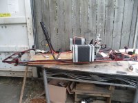
I've watched this video several times
...& the steering doesn't seem right :huh:

The car/kart seems ta be handling pretty good
...but, watch the front wheels :popcorn:

When turning, the outer wheel seems ta be turning more than, the inner one
...but, according to the "Ackermann diagram", that we looked at previously, the inner wheel should have a smaller turning radius than, the outer wheel
...so, the inner wheel should be turning "more" than, the outer wheel 🤔
SAM_4283.JPG
 

madprofessor

"Loose Cannon Creations"
Messages
2,899
Reaction score
966
Location
Jacksonville, Florida
When turning, the outer wheel seems ta be turning more than, the inner one
Camera lens angle makes it look like both front tires have a terrible case of toe-in, but that's got to be the lens doesn't it? That being a given, how much blame can be put on the lens to explain the reverse Ackermann? Not enough, it sure does look like reverse to my eyes, that's awful. I don't know nearly enough about flat-tracks to decide if there's any advantage to pushing on the outside or not.
Then there's the barely-there brakes or fear of them, whichever explains coasting into the turns instead of hitting the brakes hard on approach. Must be fear, because there's also a bad lag getting back on the gas coming through and out of the apexes, lots of time lost between those two fails.
Kudos though on getting behind the other kart and learning from it how to keep it as straight as possible through the slalom cones, some good gains there.
 

Functional Artist

Well-known member
Messages
5,640
Reaction score
3,274
Location
Toledo, Ohio
Hey, that bent up, shiny aluminum thing is kinda big to just hold a little dinky meter.
Does it do anything else? :huh:

Well, Ima glad you asked :thumbsup:

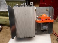
Ima using it as a mounting bracket for the speed controller, contactor & voltage indicator (ta aid in mounting these components on the kart)
&
It also, does "double duty" as a heat sink for the speed controller & contactor (ta help "draw" heat out/away from the SC & contactor)
&
It also, does "triple duty" as a protective cover for the SC & contactor (ta help protect these components from "road debris")
SAM_4495 (1).JPG
* I also, got some little stuff cleaned up & painted ;)
SAM_4486 (1).JPG
 

Functional Artist

Well-known member
Messages
5,640
Reaction score
3,274
Location
Toledo, Ohio
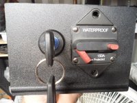
I made up the "lower" dashboard (a piece of black textured plastic, from the back of an old TV) :2guns:

A key switch (ta turn the Tractive System On or Off) will mount on the left
...& a 48V 150A circuit breaker will mount on the right (for easiest access in an emergency & ya don't have to reach over the key ta get to it)
SAM_4500 (1).JPG
Now, (finally) Ima thinkin' we're about ready ta start on re-assembly :wai:
 

Functional Artist

Well-known member
Messages
5,640
Reaction score
3,274
Location
Toledo, Ohio
RE-assembly, starts with where did I put (fill in the blank)
...& where is (fill in the blank)
...then, nope those are the bolts for (fill in the blank) :huh:

The wiring is the next "big task"
...& we've discussed what needs ta go where (in excruciating detail) :devil2:
...now, we gotta do it :thumbsup:

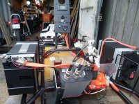
So, first I sat the batteries "in place" (ta make up some cables)
...& then, mounted the speed controller, contactor, meter assembly (ta run them J1, J2 & the dash meter harnesses)
...& also, the upper & lower dash boards (ta know how long them harnesses needed ta be)
SAM_4501 (1).JPG
Here is another view ;)
SAM_4502 (1).JPG
...& another
SAM_4503 (1).JPG
* I must say, if everything "works out", this thing should be a beast :sifone:
 

Functional Artist

Well-known member
Messages
5,640
Reaction score
3,274
Location
Toledo, Ohio
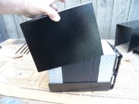
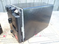
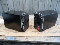
Them battery packs seemed kinda "naked" ta me :idea2:
...so, I gave 'em a "full metal jacket" :thumbsup:
SAM_4505 (1).JPG
I used some (more) of the "textured" metal from that old refrigerator
...& painted 'em with some of that Gloss Black Appliance Epoxy Paint (same as the floor board) ;)
SAM_4507 (1).JPG
Yup, that looks better to me :2guns:
SAM_4506.JPG
Ima thinkin' these should help protect 'em a bit
...& also, kinda spread out the pressure from the "U bolts" that will mount/clamp 'em down :cool:
 

Functional Artist

Well-known member
Messages
5,640
Reaction score
3,274
Location
Toledo, Ohio
I re-used some of the kool orange battery cables, I got from dismantling the Chevy Volt Battery Pack :cool:

Just had ta cut 'em to size
...& add some terminals :thumbsup:

Some of them are "flat" (not a solid bar but, like "stacked strips")
...& some are round
...but, all seem ta be (~4g.)
* Perfect for this application ;)

I "grouped" the high voltage cables together
(battery pack positive (+) up to the circuit breaker & then, back to the B+ on the speed controller & the orange key switch wire)
...& also, ran 'em thru some "looms" ta secure them to the kart (just wire tying them to the frame didn't seem proper)

** Notice the pads that will help "cushion" the ride for them batt packs :sifone:
SAM_4509 (1).JPG
I covered all high voltage (48V pack voltage) wires in an orange plastic cover
...& segregated the low voltage "signal" wires (running right next to them) in a black plastic covering :cheers2:

*** FYI: The yellow cover is protecting the "side meter's" power wire (48VDC)
SAM_4510 (1).JPG
 

Functional Artist

Well-known member
Messages
5,640
Reaction score
3,274
Location
Toledo, Ohio
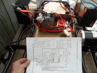
Well, I think :idea2: I got everything connected (properly) :thumbsup:

Circuit Check
So, I got the diagram out
...& double checked each & every circuit
...& then, triple checked 'em ;)
SAM_4516 (1).JPG
Everything "checked out" good :bannana:

Power Check
So, I turned on the circuit breaker (energizing the system)
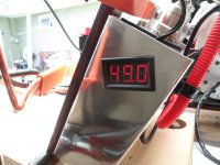
...& the "side" meter "lit up" (49.0V)
SAM_4519 (1).JPG
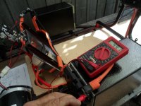
Then, when I checked (with MM) it showed about the same (49.1V) (pretty close to the "side" meter)

* Also, at this "point", I double checked that there was "power" (pack voltage) where there was supposed to be
...& not any "power" anywhere, that it wasn't supposed to be :cool:
SAM_4518 (1).JPG
System Check
Then, (with everything checking out so far) I went ahead & turned the key switch on

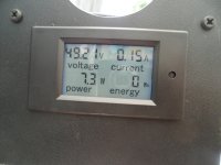
The Power Meter (on the dashboard) "lit up" (49.2V) (also, pretty close to the side meter) :cheers2:
SAM_4521.JPG
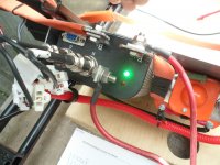
...& I heard an audible "click" from the contactor (indicating that it was "on")
...& also, the green LED light (on the controller) was "lit up" (indicating the speed controller was "on")

So, we got "Solution" as they refer to it in the Kelly Manual :2guns:
SAM_4520 (1).JPG
 

Functional Artist

Well-known member
Messages
5,640
Reaction score
3,274
Location
Toledo, Ohio
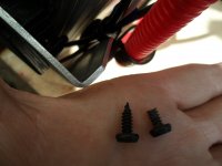
When I went to secure one of the wire looms down with a screw, I could hear my buddy Sid (Alex), way back in my left brain, reminding me that "pointy screws" can be dangerous, if the point is left exposed :worried2:

* I sure miss him 😞
...& hope he is doing well :cheers2:

So, I got rid of that point ;)
...& then, secured 'er down :thumbsup:
SAM_4514.JPG

Oh yea, I did a video to document the first bench test of the Tractive System :2guns:
 
Top