Half-breeder
"Edit" button removed
- Messages
- 1,686
- Reaction score
- 2
Ok I have fiddled w/ atleast 50-70 different scenarios/setups/positionings, studied numerous sites on the Ackerman 'reasoning', and have come up w/ an explanation/fix for the problems vs solution...
Problem w/ (most) go carts steering, that points forward(leading arms), is the lack of Ackerman(outside wheel turns more sharply than the inside... causing 1 wheel to be drug as the other grips). When taking a turn it is a 'given' that the inside wheel is not only traveling at a slower rotation... but also a 'tighter' path... so therefore, the more, tighter of a turn being made... the more the 'inside' wheel 'should' angle vs the outer.

To correct this... a 'farther' throw of the tierod, must be performed to the inside wheel, while a shorter throw, to the outside. 'This' can be performed 3 different ways...
"If" there is room the typical way to improve Ackerman is reverse the spindles to a rearward facing position, and the 'geometry' is corrected('if' mounting holes line up w/ Ackerman angle 'line' on the spindles)... Example of Ackerman w/ 'trailing' arms.
Another way to correct Ackerman(for forward facing spindles) is 'extending' the tierod connection point, on the spindle arm, 'past' the kingpin and 'outward', towards the wheels to lineup w/ the 'line' to create Ackerman...This procedure is not widely used/done, due to clearance issues...
(the one on the 'right')...

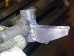
A 3rd way, which I did, because of clearance issues w/ wheels vs spindles, was take the distance that you would use for the above(2nd) example tie-rods, but move them inward instead of out, crossing them over/past the pitman arm... by using a pitman arm 'plate' to separate the 2 arm connections from each other, and create the necessary movement needed for proper Ackerman...

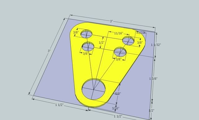
...a resemblance of the pattern I followed...
From my 'trial n errors' I found that there is a difficulty in trying to find the happy medium in creating the plate, hole placement points. Most end results are uncorrected Ackerman and/or unaligned neutral positioning, or even worse.... binding. The truth is... unless the length/width are identical... there 'is' no "set" measurements. Little bit like a wedding dress... someone could mass produce them to fit a 'set' sized bride... but EVERY bride is shaped/sized/fit different... so measurements and calculations HAVE to be done, inorder to be 'custom' and actually 'perform' properly... and even 'then' it's all about 'guesstamations' of experience, and individual preferences.... but the procedure in 'finding' said guesstamations are 'set'... Ill try to simplify my procedure...
The angled difference, from the center of the rear axle to the center of the steering spindle pivot('kingpin') of both sides, is the angle that the plate needs to imitate. To attain the angle, lay a line from said points(thread/wire/yarn/etc... has to be straight). place a paper, under the center of the rear axle, as close to the frame, where the lines meet. W/ a single light directly above, trace the shadow of the lines, creating the "V" shaped angle, to the paper. Measure up from the focal point of the "V" 3-4 inches, and cut out the "V" shape. Place template of the angle on plate, and trace the patterned angle to the plate(centered). After attaining the angle at which the holes will be aligned on the plate... the 'length' of the plate needs to be equated... too long will result in a shorter turn of the wheel to attain FULL turn(too responsive... can be dangerous)... too short and a FULL turn will not be attained(shortening of turning radius).
***Trial and error part...best to use a practice plate (I used bumper plastic)*** First, take tierod ends(ones that will be in the pitman plate) and afix a small, short nail(smaller the better...w/ a 'head' nail only needs to stick out 1/2") ONto the end of the threaded stub(the one that goes through the plate), centered, as if an 'extension' of the rod(this will help w/ the trial n errors... plus smaller holes are easier to drill than big ones). I found tape to be a suitable implement in temporarily holding said nail to the 'stub'.
...Photoshop example...

Place the plate onto position(the pivot of the angle centered to steering rod end)... clamp and drill a hole 'below' the 'single' hole that 'was' the tierod end mounting point on the factory pitman arm...(NO WELD!!!...This will create a strong enough mounting even for driving!)

Drill 2 small holes(diameter of the nail) next to each other, on the angled lines(1 each line). Place nails into the holes(opposing sides) and set steering wheel at neutral position(straight ahead). Set the alignment. Then, remove nails, turn the steering, replace nails, and view from above, to check the Ackerman. If Ackerman is not suitable... remove nails from holes and redrill either above or below the current hole, keeping the new hole beside the new hole on the opposite side... staying on the 'line'... repeat till satisfied. Once position is attained... drill 'appropriate' holes larger to accommodate tierod ends. Shims/washers 'may' be needed dependent on the nuts used and the plate thickness(Lock tight 'red' after all is situated... no need for lock washers).
Also, the spindle arms themselves play a vital role in turning radius w/ proper Ackerman. Most karts will have spindles that have arms that are not 90degrees off the steering knuckle, they will be angled 'inwards'(factory false hypothesis of a 'fix' of Ackerman). The actual arms themselves will hinder turning radius(the angle amount, that the wheel turns) by making contact w/ the pivot bracket, hindering it from traveling any further.
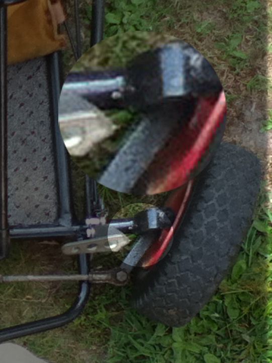
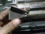
Another 'issue' is clearance of the opposing arms that cross each other on the pitman plate. Alotta times it is found that the nuts/extending bolts, will hinder free travel of the tierod ends and cause binding... there for a 'low-profile' nut and a shortened bolt 'should' be implemented to clear each other in a turn...
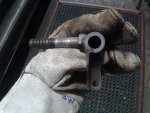
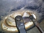
...protruding bolt hindering arm travel/swing...

...proper nut/bolt clearance...

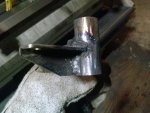
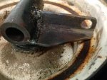
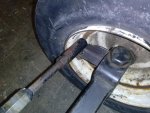
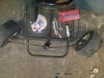
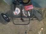
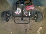
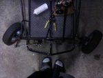
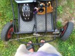
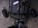
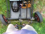
After all is said and done(if done correctly), turns should be MUCH more effective and should appear somewhat like the attachments of this thread...Ackermann corrected.
Attachments are before and after(daylight=before/darker=after)
Problem w/ (most) go carts steering, that points forward(leading arms), is the lack of Ackerman(outside wheel turns more sharply than the inside... causing 1 wheel to be drug as the other grips). When taking a turn it is a 'given' that the inside wheel is not only traveling at a slower rotation... but also a 'tighter' path... so therefore, the more, tighter of a turn being made... the more the 'inside' wheel 'should' angle vs the outer.
To correct this... a 'farther' throw of the tierod, must be performed to the inside wheel, while a shorter throw, to the outside. 'This' can be performed 3 different ways...
"If" there is room the typical way to improve Ackerman is reverse the spindles to a rearward facing position, and the 'geometry' is corrected('if' mounting holes line up w/ Ackerman angle 'line' on the spindles)... Example of Ackerman w/ 'trailing' arms.
Another way to correct Ackerman(for forward facing spindles) is 'extending' the tierod connection point, on the spindle arm, 'past' the kingpin and 'outward', towards the wheels to lineup w/ the 'line' to create Ackerman...This procedure is not widely used/done, due to clearance issues...
(the one on the 'right')...
A 3rd way, which I did, because of clearance issues w/ wheels vs spindles, was take the distance that you would use for the above(2nd) example tie-rods, but move them inward instead of out, crossing them over/past the pitman arm... by using a pitman arm 'plate' to separate the 2 arm connections from each other, and create the necessary movement needed for proper Ackerman...
...a resemblance of the pattern I followed...
From my 'trial n errors' I found that there is a difficulty in trying to find the happy medium in creating the plate, hole placement points. Most end results are uncorrected Ackerman and/or unaligned neutral positioning, or even worse.... binding. The truth is... unless the length/width are identical... there 'is' no "set" measurements. Little bit like a wedding dress... someone could mass produce them to fit a 'set' sized bride... but EVERY bride is shaped/sized/fit different... so measurements and calculations HAVE to be done, inorder to be 'custom' and actually 'perform' properly... and even 'then' it's all about 'guesstamations' of experience, and individual preferences.... but the procedure in 'finding' said guesstamations are 'set'... Ill try to simplify my procedure...
The angled difference, from the center of the rear axle to the center of the steering spindle pivot('kingpin') of both sides, is the angle that the plate needs to imitate. To attain the angle, lay a line from said points(thread/wire/yarn/etc... has to be straight). place a paper, under the center of the rear axle, as close to the frame, where the lines meet. W/ a single light directly above, trace the shadow of the lines, creating the "V" shaped angle, to the paper. Measure up from the focal point of the "V" 3-4 inches, and cut out the "V" shape. Place template of the angle on plate, and trace the patterned angle to the plate(centered). After attaining the angle at which the holes will be aligned on the plate... the 'length' of the plate needs to be equated... too long will result in a shorter turn of the wheel to attain FULL turn(too responsive... can be dangerous)... too short and a FULL turn will not be attained(shortening of turning radius).
***Trial and error part...best to use a practice plate (I used bumper plastic)*** First, take tierod ends(ones that will be in the pitman plate) and afix a small, short nail(smaller the better...w/ a 'head' nail only needs to stick out 1/2") ONto the end of the threaded stub(the one that goes through the plate), centered, as if an 'extension' of the rod(this will help w/ the trial n errors... plus smaller holes are easier to drill than big ones). I found tape to be a suitable implement in temporarily holding said nail to the 'stub'.
...Photoshop example...
Place the plate onto position(the pivot of the angle centered to steering rod end)... clamp and drill a hole 'below' the 'single' hole that 'was' the tierod end mounting point on the factory pitman arm...(NO WELD!!!...This will create a strong enough mounting even for driving!)
Drill 2 small holes(diameter of the nail) next to each other, on the angled lines(1 each line). Place nails into the holes(opposing sides) and set steering wheel at neutral position(straight ahead). Set the alignment. Then, remove nails, turn the steering, replace nails, and view from above, to check the Ackerman. If Ackerman is not suitable... remove nails from holes and redrill either above or below the current hole, keeping the new hole beside the new hole on the opposite side... staying on the 'line'... repeat till satisfied. Once position is attained... drill 'appropriate' holes larger to accommodate tierod ends. Shims/washers 'may' be needed dependent on the nuts used and the plate thickness(Lock tight 'red' after all is situated... no need for lock washers).
Also, the spindle arms themselves play a vital role in turning radius w/ proper Ackerman. Most karts will have spindles that have arms that are not 90degrees off the steering knuckle, they will be angled 'inwards'(factory false hypothesis of a 'fix' of Ackerman). The actual arms themselves will hinder turning radius(the angle amount, that the wheel turns) by making contact w/ the pivot bracket, hindering it from traveling any further.
Another 'issue' is clearance of the opposing arms that cross each other on the pitman plate. Alotta times it is found that the nuts/extending bolts, will hinder free travel of the tierod ends and cause binding... there for a 'low-profile' nut and a shortened bolt 'should' be implemented to clear each other in a turn...
...protruding bolt hindering arm travel/swing...
...proper nut/bolt clearance...
After all is said and done(if done correctly), turns should be MUCH more effective and should appear somewhat like the attachments of this thread...Ackermann corrected.
Attachments are before and after(daylight=before/darker=after)
Attachments
-
 1015132014a.jpg68.7 KB · Views: 138
 -
 002.JPG379.9 KB · Views: 150
 -
 1015132015.jpg66.8 KB · Views: 139
 -
 003 (2).JPG373.1 KB · Views: 183
")


 yep, got more grip turning hard right than hard left....