Building a go kart size Aerial Atom

Functional Artist

Well-known member
Messages
4,411
Reaction score
1,694
Location
Toledo, Ohio
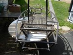
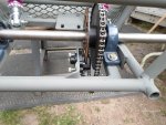
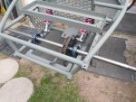
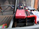
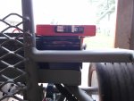
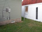
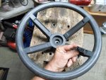
Startin' to get stuff primed & "sealed" up :thumbsup:

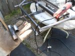
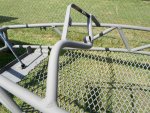
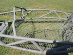
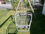
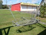
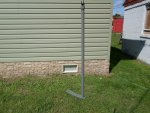
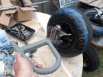
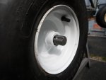
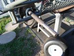
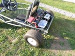
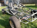
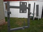
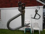
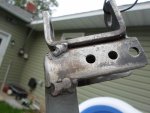
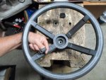
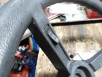
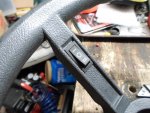
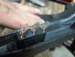
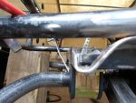
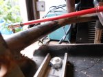
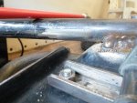
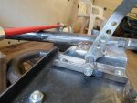
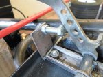
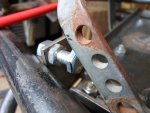
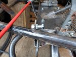
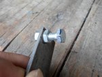
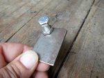
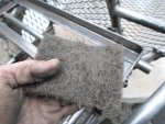
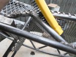
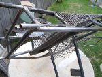
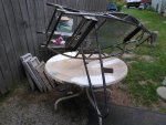
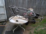
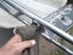
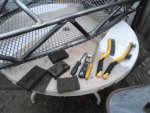
After some wire brushin' & scrubbin' & sandin' & final wipe down, I hung the swing arm, the speed controller mounting plate, the battyery hold down bracket, the A-frames & the pedal mounting brackets.
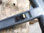
…& then, gave everything a good coat of self etching primer :cheers2:
(etching-helps it to "bite" into or "adhere" onto bare metal)

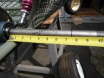
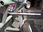
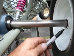
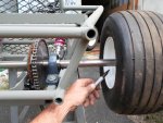
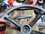
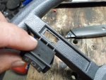
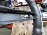
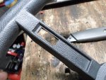
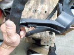
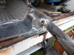
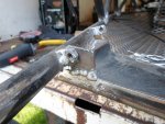
* Except, I left the ends of the A-frames "exposed" or bare :cool:
(I didn't want to coat/contaminate the spindle mounting area, if/when I weld 'er up solid)
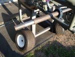
 

Attachments

  • SAM_2612.jpg
    SAM_2612.jpg
    399.2 KB · Views: 4
  • SAM_2614.jpg
    SAM_2614.jpg
    331 KB · Views: 4
  • SAM_2872.jpg
    SAM_2872.jpg
    213.8 KB · Views: 4
  • SAM_2873.jpg
    SAM_2873.jpg
    313.4 KB · Views: 3
  • SAM_2875.jpg
    SAM_2875.jpg
    226.9 KB · Views: 3

Functional Artist

Well-known member
Messages
4,411
Reaction score
1,694
Location
Toledo, Ohio
While that stuff was dryin', I worked on the steering wheel
...'er added some switches to the steering wheel :thumbsup:

I am gonna use a standard 12VDC 20A automotive type switch to turn the speed controller On/Off
…& a 125VAC 20A On/Off/On switch to toggle from forward to reverse

The ON/Off circuit is "pack voltage" (~60V nominal) actually, it should top out ~ 66.5V fully charged
...but, when I tested, it only carries ~14.5mA

From extensive research, I have come to the conclusion that most any switch that can handle 20A @ 12VDC
...should be able to handle less than .5A (1/2 of an amp) @ 60VDC
* But, this is just my opinion

Even thinkin' it thru, worst case scenario, if the switch fails the SC would just be stuck "powered on"
...or stuck "powered off"
...but, no imminent danger :rolleyes:

The SC would still act/operate as normal
...if stuck "off" the system would be off
...if stuck "on" the system would be on
...but, it would not "take off" or be "self powering" or anything
…& the throttle would still operate as normal too :wai:

The forward/reverse circuit tested to only ~4.5V
(IMO most any switch should be able to handle 4.5VDC so, I didn't even bother to check the Amp draw)

The first "On" will signal the controller to operate the motor to go forward
…in the middle "Off" will be kinda like Neutral
…the second "On" will signal the SC to operate the motor in reverse


So, it looks like these switches will fit into the indent slots in the "bars" of the steering wheel :cheers2:
...then, I marked 'em & started drillin' some holes

I was thinkin to put 'em toward the bottom, at first
...but, now I'm thinkin' "up top", thumb actuated will be best :2guns:
 

Attachments

  • SAM_2794.jpg
    SAM_2794.jpg
    326.2 KB · Views: 3
  • SAM_2802.jpg
    SAM_2802.jpg
    208.2 KB · Views: 3
  • SAM_2791.jpg
    SAM_2791.jpg
    215.2 KB · Views: 3
  • SAM_2803.jpg
    SAM_2803.jpg
    222.6 KB · Views: 3
  • SAM_2797.jpg
    SAM_2797.jpg
    237.7 KB · Views: 4
  • SAM_2811.jpg
    SAM_2811.jpg
    381.4 KB · Views: 3
  • SAM_2807.jpg
    SAM_2807.jpg
    258.5 KB · Views: 3
  • SAM_2793.jpg
    SAM_2793.jpg
    361.8 KB · Views: 3

Shep1970

Member
Messages
72
Reaction score
4
Location
Massachusetts
Nice, I’ve been using a simple 12v atv key switch just for power on (works fine) mind you this is not the main breaker also like in your system. Alright I didn’t want to interrupt, it’s coming together nicely.

Shep
 

Functional Artist

Well-known member
Messages
4,411
Reaction score
1,694
Location
Toledo, Ohio
Nice, I’ve been using a simple 12v atv key switch just for power on (works fine) mind you this is not the main breaker also like in your system. Alright I didn’t want to interrupt, it’s coming together nicely. Shep

Yup, almost all of my karts have "cheap Chinese" scooter type key switches
…& I've never had a problem :thumbsup:

But, here we are workin' with almost 72VDC
...so, I'm being extra/more cautious
...& also don't want to give false/bad advise :cheers2:

To clarify, the 150VDC 50A circuit breaker (the one in the multi-meter box, now)
...is the "main" breaker (the "big" power/amperage goes thru this one)

The On/Off switch (the one on the steering wheel) is "small" power
...& just "signals" the SC to turn "on or off" upon request :2guns:
 

Functional Artist

Well-known member
Messages
4,411
Reaction score
1,694
Location
Toledo, Ohio
A little whittlin'
...& Boom :2guns:

We got switches, well within reach :thumbsup:

Kinda looks like they supposed to be there :cheers2:

* I angled the terminals on the switches so, they "lean" toward the center
...as to keep the wiring "in close"

** To "illuminate" when the On/Off switch is "switched" on, I "colored" the exposed edge of the switch
...just used a gold sharpie :cool:
 

Attachments

  • SAM_2812.jpg
    SAM_2812.jpg
    346.5 KB · Views: 2
  • SAM_2813.jpg
    SAM_2813.jpg
    308.3 KB · Views: 2
  • SAM_2835.jpg
    SAM_2835.jpg
    358 KB · Views: 3
  • SAM_2820.jpg
    SAM_2820.jpg
    235.8 KB · Views: 2
  • SAM_2819.jpg
    SAM_2819.jpg
    282.2 KB · Views: 2
  • SAM_2815.jpg
    SAM_2815.jpg
    306.8 KB · Views: 2
  • SAM_2814.jpg
    SAM_2814.jpg
    316.4 KB · Views: 2
  • SAM_2823.jpg
    SAM_2823.jpg
    238.1 KB · Views: 2
  • SAM_2837.jpg
    SAM_2837.jpg
    282.8 KB · Views: 2
  • SAM_2833.jpg
    SAM_2833.jpg
    240.8 KB · Views: 2

Functional Artist

Well-known member
Messages
4,411
Reaction score
1,694
Location
Toledo, Ohio
While cleanin' up the "main frame", I noticed/remembered that the front edge of the A-frame mount didn't quite reach up to the frame rails & could use/needed some extra support :huh:

At first, I was thinkin' to use a piece of pipe
...but, that's kinda "over doin' it"

Then I was thinkin', we need some "pedal stops" too
…so, maybe we can go "dual purpose" :thumbsup:

I rounded up some 1/8" steel
...cut a couple of pieces of ~1 1/2" x 2"
…drilled 5/16" holes in 'em (in the appropriate spots)
…& added some 5/16" nuts-n-bolts to use as the adjustable "stops" :cheers2:
 

Attachments

  • SAM_2847.jpg
    SAM_2847.jpg
    251.1 KB · Views: 4
  • SAM_2846.jpg
    SAM_2846.jpg
    238.2 KB · Views: 4
  • SAM_2845.jpg
    SAM_2845.jpg
    209.1 KB · Views: 4
  • SAM_2844.jpg
    SAM_2844.jpg
    286.6 KB · Views: 4
  • SAM_2843.jpg
    SAM_2843.jpg
    259.3 KB · Views: 3
  • SAM_2860.jpg
    SAM_2860.jpg
    306.9 KB · Views: 4
  • SAM_2857.jpg
    SAM_2857.jpg
    258.5 KB · Views: 4
  • SAM_2855.jpg
    SAM_2855.jpg
    299.1 KB · Views: 4
  • SAM_2854.jpg
    SAM_2854.jpg
    203.9 KB · Views: 4
  • SAM_2852.jpg
    SAM_2852.jpg
    273.7 KB · Views: 4

Tpdingo

Member
Messages
903
Reaction score
1
Location
Bellmore, NY
While cleanin' up the "main frame", I noticed/remembered that the front edge of the A-frame mount didn't quite reach up to the frame rails & could use/needed some extra support :huh:

At first, I was thinkin' to use a piece of pipe
...but, that's kinda "over doin' it"

Then I was thinkin', we need some "pedal stops" too
…so, maybe we can go "dual purpose" :thumbsup:

I rounded up some 1/8" steel
...cut a couple of pieces of ~1 1/2" x 2"
…drilled 5/16" holes in 'em (in the appropriate spots)
…& added some 5/16" nuts-n-bolts to use as the adjustable "stops" :cheers2:

I hope those are lock nuts or your foot is going to the floor.
 

Functional Artist

Well-known member
Messages
4,411
Reaction score
1,694
Location
Toledo, Ohio
I hope those are lock nuts or your foot is going to the floor.

I welded 'em on
...so, their kinda "locked" (I guess you could call it) :lolgoku:
...but, the "cinch" nuts on back side should "lock" the pedal stop bolts "in place" :thumbsup:
 

Attachments

  • SAM_2909.jpg
    SAM_2909.jpg
    264.9 KB · Views: 4
  • SAM_2910.jpg
    SAM_2910.jpg
    271.9 KB · Views: 4

Functional Artist

Well-known member
Messages
4,411
Reaction score
1,694
Location
Toledo, Ohio
Cleanin' & cleanin' & cleanin' & cleanin'
...& cleanin' some more :huh:

I've used a scraper, a file, wire brushes, wire wheel, sand paper, sanding sponges, emery cloth
...& even some paint stripping pads :cheers2:

I've worked on 'er for a couple of hours here & a couple of hours there
...but, it's still not quite clean enough :ack2: (for my likin' :thumbsup: )

There are just so many "surfaces" & "nooks-n-crannies" :furious2:
 

Attachments

  • SAM_3280.jpg
    SAM_3280.jpg
    327.7 KB · Views: 5
  • SAM_3274.jpg
    SAM_3274.jpg
    281.7 KB · Views: 5
  • SAM_3270.jpg
    SAM_3270.jpg
    402.5 KB · Views: 5
  • SAM_3269.jpg
    SAM_3269.jpg
    400.7 KB · Views: 5
  • SAM_3267.jpg
    SAM_3267.jpg
    401.2 KB · Views: 6
  • SAM_3277.jpg
    SAM_3277.jpg
    252 KB · Views: 4
  • SAM_3281.jpg
    SAM_3281.jpg
    300.5 KB · Views: 4

Functional Artist

Well-known member
Messages
4,411
Reaction score
1,694
Location
Toledo, Ohio
Another couple of hours of smoothin' & deburrin'
…& I think we are "finally" about there :wai:

Also, cut/trimmed the frame "nubs" off :thumbsup:

I wiped everything down "good" with degreaser
...but, what about ALL of these "nooks-n-crannies" that I can't get in to? :huh:
…& it's too big to do a "dunk" type rinse

:idea2: maybe just "hose 'er down" (to get into & kinda wash everything out)
...& then, just let 'er "drip dry" :cheers2:

So, I put some of the degreaser into a "pump action" spray bottle
…& gave 'er a "spray bath" :2guns:
 

Attachments

  • SAM_3287.jpg
    SAM_3287.jpg
    437.8 KB · Views: 5
  • SAM_3286.jpg
    SAM_3286.jpg
    438 KB · Views: 3
  • SAM_3285.jpg
    SAM_3285.jpg
    378.2 KB · Views: 3
  • SAM_3284.jpg
    SAM_3284.jpg
    314.6 KB · Views: 3
  • SAM_3282.jpg
    SAM_3282.jpg
    409.4 KB · Views: 3

Functional Artist

Well-known member
Messages
4,411
Reaction score
1,694
Location
Toledo, Ohio
I finally got the main frame all sealed up :thumbsup:

I removed the steering shaft & primed it separately :cheers2:

* added a layer of masking tape, to keep the primer out of the splines, that the steering wheel slide on to
…& it held the spacer nicely for priming too :2guns:
 

Attachments

  • SAM_3299.jpg
    SAM_3299.jpg
    664.1 KB · Views: 4
  • SAM_3298.jpg
    SAM_3298.jpg
    677.7 KB · Views: 4
  • SAM_3292.jpg
    SAM_3292.jpg
    621.2 KB · Views: 4
  • SAM_3291.jpg
    SAM_3291.jpg
    627.9 KB · Views: 6
  • SAM_3288.jpg
    SAM_3288.jpg
    436.5 KB · Views: 4
  • SAM_3289.jpg
    SAM_3289.jpg
    193.3 KB · Views: 4
  • SAM_3290.jpg
    SAM_3290.jpg
    152.4 KB · Views: 4

Functional Artist

Well-known member
Messages
4,411
Reaction score
1,694
Location
Toledo, Ohio
I'm gonna assemble everything & do some testin', before we give 'er a nice paint job. :thumbsup:

So, I worked the front suspension first
...A-frames
...spindles
...spring/shock absorbers
...wheels

Then, started on the swing arm, in the rear
...spring/shock absorbers
...bearings
...axle
...sp-rotor (I was told, by my local go kart parts supplier, this is a 60's term, meaning a sprocket/rotor combo)
...caliper

When, I went to put the wheels on, I remembered that we need to make some "spacers" to keep 'em in place
 

Attachments

  • SAM_3338.jpg
    SAM_3338.jpg
    327.2 KB · Views: 4
  • SAM_3335.jpg
    SAM_3335.jpg
    402.3 KB · Views: 3
  • SAM_3333.jpg
    SAM_3333.jpg
    394.8 KB · Views: 4
  • SAM_3332.jpg
    SAM_3332.jpg
    472.4 KB · Views: 3
  • SAM_3330.jpg
    SAM_3330.jpg
    360.9 KB · Views: 2
  • SAM_3339.jpg
    SAM_3339.jpg
    317.6 KB · Views: 3

Functional Artist

Well-known member
Messages
4,411
Reaction score
1,694
Location
Toledo, Ohio
Spacers

To make the spacers
(It's kinda difficult to get an accurate measurement with the wheel in place)

So, I went about it another way :cheers2:

First, I made sure axle was centered
...put the wheels exactly where they needed to be
...made sure there was adequate threads for securing the wheel
...marked the axle
…& then, simply measured the distance between the marks :thumbsup:
 

Attachments

  • SAM_3345.jpg
    SAM_3345.jpg
    281.4 KB · Views: 2
  • SAM_3343.jpg
    SAM_3343.jpg
    394.4 KB · Views: 2
  • SAM_3342.jpg
    SAM_3342.jpg
    173.5 KB · Views: 2
  • SAM_3341.jpg
    SAM_3341.jpg
    269.4 KB · Views: 2
  • SAM_3340.jpg
    SAM_3340.jpg
    319.2 KB · Views: 2

Functional Artist

Well-known member
Messages
4,411
Reaction score
1,694
Location
Toledo, Ohio
I chopped a couple of 1" ID. pieces of steel tube @ ~7 1/2" (with metal cut-off saw)
…& then, de-burred the ends a bit (with the grinder)

Installed the "keys"
...then, slid the wheels on
…& tightened the "retaining nuts" :thumbsup:
 

Attachments

  • SAM_3346.jpg
    SAM_3346.jpg
    342.6 KB · Views: 3
  • SAM_3348.jpg
    SAM_3348.jpg
    486.9 KB · Views: 3
  • SAM_3349.jpg
    SAM_3349.jpg
    426.3 KB · Views: 4
  • SAM_3353.jpg
    SAM_3353.jpg
    170.2 KB · Views: 3
  • SAM_3354.jpg
    SAM_3354.jpg
    186.8 KB · Views: 3

Functional Artist

Well-known member
Messages
4,411
Reaction score
1,694
Location
Toledo, Ohio
a slight deversion

While tightening the retaining nuts, on the rear axle, the 1/2" driver bit snapped off
...pretty much "flush" with the bit holder :ack2:

I tried everything, that I could think of
...but, couldn't get a good "bite" on it :huh:

:idea2: maybe try the "welded nut" trick

So, I sat a 5/16" nut, on the end of the bit holder, over the broke off piece
...held it "in place" with the ground clamp

Starting from the inside bottom, I filled in/welded the end of the broke off piece, to the nut :thumbsup:
…& then, used that "nut" as a "handle" to extract the piece :2guns:

The heat from welding may have kinda expanded the bit holder, aiding the release

* Kinda accidentally welded it to my ground clamp
…& then, had to pour some coffee on the bit holder, for a quick kool down :cheers2:
 

Attachments

  • SAM_3361.jpg
    SAM_3361.jpg
    430.7 KB · Views: 1
  • SAM_3360.jpg
    SAM_3360.jpg
    511.2 KB · Views: 4
  • SAM_3359.jpg
    SAM_3359.jpg
    190.8 KB · Views: 2
  • SAM_3358.jpg
    SAM_3358.jpg
    190.9 KB · Views: 3
  • SAM_3357.jpg
    SAM_3357.jpg
    230 KB · Views: 2

Functional Artist

Well-known member
Messages
4,411
Reaction score
1,694
Location
Toledo, Ohio
I installed the motor & chain
…& the speed controller & connection box

Then, commenced getting all of the wiring ran, to where it goes
...& everything connected up :thumbsup:
 

Attachments

  • SAM_3362.jpg
    SAM_3362.jpg
    273.6 KB · Views: 3
  • SAM_3365.jpg
    SAM_3365.jpg
    304.4 KB · Views: 4
  • SAM_3366.jpg
    SAM_3366.jpg
    276.4 KB · Views: 2
  • SAM_3367.jpg
    SAM_3367.jpg
    189.4 KB · Views: 2

Functional Artist

Well-known member
Messages
4,411
Reaction score
1,694
Location
Toledo, Ohio
We got power

Installed the (5) 12V 15AH Mighty Max batteries
…& clamped 'em in-place with the battery hold down :thumbsup:

Then, used some Industrial Velcro to secure/mount the circuit breaker on to battery #1 :cheers2:

This circuit breaker is the "main cut-off" for the whole system :cheers2:

So, this way it's easy to visually located
...& easily accessible

Plus (+), (he he, I made an electrical pun) :lolgoku: the positive battery cables are "short & sweet"
...battery (+) terminal to CB (in)
...& CB (out) to speed controller battery (+) :2guns:
 

Attachments

  • SAM_3389.jpg
    SAM_3389.jpg
    206.7 KB · Views: 1
  • SAM_3391.jpg
    SAM_3391.jpg
    291.2 KB · Views: 2
  • SAM_3375.jpg
    SAM_3375.jpg
    345.7 KB · Views: 2
  • SAM_3370.jpg
    SAM_3370.jpg
    328.1 KB · Views: 2
  • SAM_3369.jpg
    SAM_3369.jpg
    196.2 KB · Views: 2
  • SAM_3397.jpg
    SAM_3397.jpg
    244 KB · Views: 2
  • SAM_3398.jpg
    SAM_3398.jpg
    232.2 KB · Views: 2
  • SAM_3399.jpg
    SAM_3399.jpg
    264.8 KB · Views: 2
  • SAM_3401.jpg
    SAM_3401.jpg
    192.8 KB · Views: 1

Functional Artist

Well-known member
Messages
4,411
Reaction score
1,694
Location
Toledo, Ohio
Kinda gettin' things wrapped up a bit :thumbsup:

Installed the seat :cheers2:

She is about ready to test run just waitin' on some cables, to connect
...the thumb throttle to the pedal
...& also the caliper to the brake pedal

Gotta be able to, get 'er goin' :auto:
…& then, be able to stop too :lolgoku:


A systems check is next :cheers2:
 

Attachments

  • SAM_3416.jpg
    SAM_3416.jpg
    629 KB · Views: 3
  • SAM_3413.jpg
    SAM_3413.jpg
    734.5 KB · Views: 3
  • SAM_3407.jpg
    SAM_3407.jpg
    738.5 KB · Views: 1
  • SAM_3409.jpg
    SAM_3409.jpg
    575.1 KB · Views: 1
  • SAM_3419.jpg
    SAM_3419.jpg
    415.5 KB · Views: 3
  • SAM_3418.jpg
    SAM_3418.jpg
    498.2 KB · Views: 1
Top