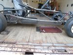
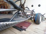
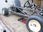
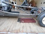
Building a go kart size Aerial Atom

bthompson224

New member
Messages
298
Reaction score
3
Location
DFW
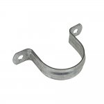
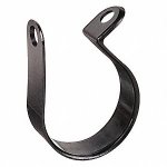
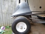
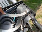
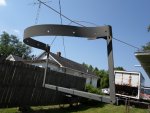
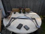
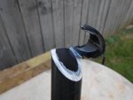
Use tube straps. They have the 180 degree ones and the full wrap 360 degree ones. Zero mods to the frame to mount, they mount to the scoop only. Pics for example only.
 

Attachments

  • oatey-pipe-hangers-33500-64_1000.jpg
    oatey-pipe-hangers-33500-64_1000.jpg
    29 KB · Views: 1
  • 30VX51_AS02.jpg
    30VX51_AS02.jpg
    12.9 KB · Views: 84

Functional Artist

Well-known member
Messages
5,599
Reaction score
3,203
Location
Toledo, Ohio
Use tube straps. They have the 180 degree ones and the full wrap 360 degree ones. Zero mods to the frame to mount, they mount to the scoop only. Pics for example only.

Maybe a possibility :thumbsup:

I use the 360* type straps for mounting/routing the hydraulic hoses on my tow trucks.

Still workin' on that
...& gotta get some metal :cheers2:

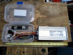
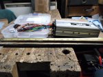
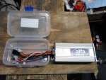
Until then, I was figurin' on where/how to mount the speed controller/connectors/wiring :idea2:
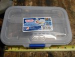
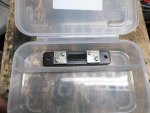
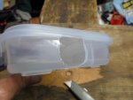
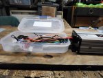
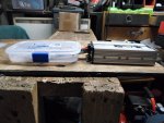
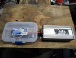
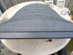
…& found this plastic pencil box @ Walmart (~$2.00) (~9" x 6" x 1 1/2")

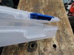
It's pretty sturdy, with a strong latch & even a separate compartment that the 50A shunt fits into nicely :wai:
 

Attachments

  • SAM_2030.jpg
    SAM_2030.jpg
    271.5 KB · Views: 1
  • SAM_2032.jpg
    SAM_2032.jpg
    252.3 KB · Views: 1
  • SAM_2037.jpg
    SAM_2037.jpg
    212.2 KB · Views: 1
  • SAM_2040.jpg
    SAM_2040.jpg
    299.8 KB · Views: 2
  • SAM_2042.jpg
    SAM_2042.jpg
    300.2 KB · Views: 1

Functional Artist

Well-known member
Messages
5,599
Reaction score
3,203
Location
Toledo, Ohio
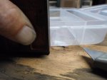
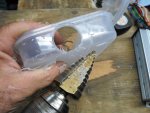
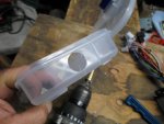
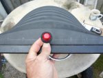
Used a step drill bit to ream out a nice hole
...pilot hole, small step bit & then, the bigger step bit :thumbsup:

I enlarged the hole up to/just until the edge of the lid
...so, as to not weaken it

The lid has a nice lip that kinda helps maintain the overall structure
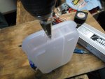
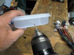
…& i'm already choppin' a big hole into the side of the box :cheers2:

Then, I used a square & knife to extend the hole
...to allow the wiring to drop thru

That'll keep all of our connections clean, dry, safe & nice-n-tidy too :2guns:
 

Attachments

  • SAM_2051.jpg
    SAM_2051.jpg
    206.6 KB · Views: 0
  • SAM_2048.jpg
    SAM_2048.jpg
    271.5 KB · Views: 0
  • SAM_2045.jpg
    SAM_2045.jpg
    186.2 KB · Views: 0
  • SAM_2044.jpg
    SAM_2044.jpg
    237.5 KB · Views: 1
  • SAM_2043.jpg
    SAM_2043.jpg
    249.6 KB · Views: 0
  • SAM_2053.jpg
    SAM_2053.jpg
    170.3 KB · Views: 0
  • SAM_2054.jpg
    SAM_2054.jpg
    298.5 KB · Views: 1
  • SAM_2055.jpg
    SAM_2055.jpg
    273.7 KB · Views: 0
  • SAM_2056.jpg
    SAM_2056.jpg
    268.5 KB · Views: 0
  • SAM_2057.jpg
    SAM_2057.jpg
    291.5 KB · Views: 1

Functional Artist

Well-known member
Messages
5,599
Reaction score
3,203
Location
Toledo, Ohio
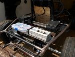
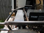
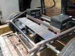
Should be able to just mount 'em on a shelf right behind the battery box :thumbsup:

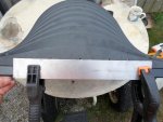
A piece of 4" wide 16g. (~1/16") steel, mounted across the upper frame rails
...will support/hold the speed controller & the wiring connector box well :cheers2:

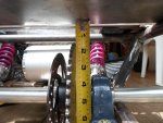
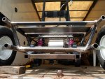
It looks like this metal shelf easily clears the sprocket/chain
...will act as a heatsink (to help dissipate SC heat)
…& will also provide the SC & wiring box some protection from the chain/sprocket/axle :2guns:
 

Attachments

  • SAM_2065.jpg
    SAM_2065.jpg
    315.4 KB · Views: 2
  • SAM_2061.jpg
    SAM_2061.jpg
    315.1 KB · Views: 1
  • SAM_2060.jpg
    SAM_2060.jpg
    357.5 KB · Views: 1
  • SAM_2064.jpg
    SAM_2064.jpg
    293.5 KB · Views: 1
  • SAM_2059.jpg
    SAM_2059.jpg
    381.1 KB · Views: 1

Functional Artist

Well-known member
Messages
5,599
Reaction score
3,203
Location
Toledo, Ohio
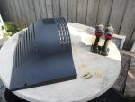
I got some metal :thumbsup:

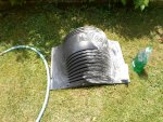
Before we can construct a sub frame for the cover
...we gotta have it fitted to exactly where it's to be mounted

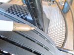
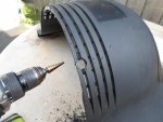
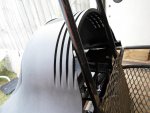
First lets "snug" it up to the seat back bars a bit

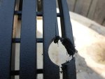
Marked 'em & used the step drills to ream out some holes
(got a minor crack but, shouldn't be a problem) :furious2:

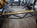
Next, I used a straight edge & a gold marker to "highlight the material that need removing

Then, a little cuttin', to removed some of the excess material
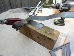
…& some light "body work" with the grinder to clean 'er up :cheers2:

Yup, that looks pretty snug :2guns:
 

Attachments

  • SAM_2117.jpg
    SAM_2117.jpg
    357.4 KB · Views: 1
  • SAM_2116.jpg
    SAM_2116.jpg
    258.7 KB · Views: 1
  • SAM_2118.jpg
    SAM_2118.jpg
    296.8 KB · Views: 1
  • SAM_2122.jpg
    SAM_2122.jpg
    328.6 KB · Views: 1
  • SAM_2131.jpg
    SAM_2131.jpg
    296.1 KB · Views: 1
  • SAM_2148.jpg
    SAM_2148.jpg
    236.8 KB · Views: 2
  • SAM_2147.jpg
    SAM_2147.jpg
    347.9 KB · Views: 1
  • SAM_2143.jpg
    SAM_2143.jpg
    336.2 KB · Views: 1
  • SAM_2140.jpg
    SAM_2140.jpg
    359.4 KB · Views: 1
  • SAM_2137.jpg
    SAM_2137.jpg
    306.5 KB · Views: 1

Functional Artist

Well-known member
Messages
5,599
Reaction score
3,203
Location
Toledo, Ohio
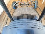
Before we move on, lets check the "stance" or look :cheers2:

I like the way it looks when the cover is sittin' (almost) right on the frame, in the front
…& ~1" above the frame, in the rear :thumbsup:

Notice, the cover's "body lines" seem to follow the frames "body lines" pretty good
…& the tires will still clear nicely too (even within full suspension travel) :2guns:

* If it's mounted with the rear higher up, the top will be "more level"
...but, I just don't think it looks right :ack2:
 

Attachments

  • SAM_2159.jpg
    SAM_2159.jpg
    326 KB · Views: 2
  • SAM_2156.jpg
    SAM_2156.jpg
    336.4 KB · Views: 2
  • SAM_2154.jpg
    SAM_2154.jpg
    348.1 KB · Views: 3
  • SAM_2157.jpg
    SAM_2157.jpg
    334 KB · Views: 3
  • SAM_2153.jpg
    SAM_2153.jpg
    324.8 KB · Views: 2

Functional Artist

Well-known member
Messages
5,599
Reaction score
3,203
Location
Toledo, Ohio
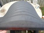
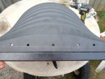
While designing a sub frame, to help support the rear cover, I noticed that there is a nice flat area in the back :idea2:

Hmmmm
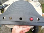
...maybe a good place for the brake lights :thumbsup:

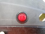
This 60V system is gonna need (5) 12V bulbs wired in series.

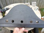
I measured, marked the light locations
…& then, used a straight edge to help "keep 'em in line"

I put (1) on each end, (1) in the middle & centered the other (2)
...but, kept 'em kinda closer to the outer ones :cheers2:

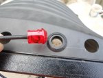
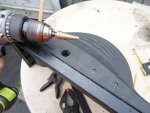
Then, used a step drill bit to enlarge the holes to 3/4"

Yup, that should work :2guns:
 

Attachments

  • SAM_2166.jpg
    SAM_2166.jpg
    294.1 KB · Views: 1
  • SAM_2168.jpg
    SAM_2168.jpg
    226.8 KB · Views: 1
  • SAM_2169.jpg
    SAM_2169.jpg
    291.8 KB · Views: 1
  • SAM_2171.jpg
    SAM_2171.jpg
    293.8 KB · Views: 1
  • SAM_2173.jpg
    SAM_2173.jpg
    283.3 KB · Views: 1
  • SAM_2180.jpg
    SAM_2180.jpg
    477.2 KB · Views: 1
  • SAM_2178.jpg
    SAM_2178.jpg
    306.3 KB · Views: 1
  • SAM_2177.jpg
    SAM_2177.jpg
    312 KB · Views: 1
  • SAM_2176.jpg
    SAM_2176.jpg
    301.6 KB · Views: 1
  • SAM_2174.jpg
    SAM_2174.jpg
    261.5 KB · Views: 1

Functional Artist

Well-known member
Messages
5,599
Reaction score
3,203
Location
Toledo, Ohio
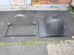
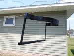
Gettin' back to the sub frame :thumbsup:

A piece of 1" square tube, with a kool wrinkle finish on it, will make for a good-n-strong rear support bar
(it will also "prop" the rear up a bit, to help lineup the "body lines")

A couple pieces of 1" x 1/8" steel, will strengthen the bottom sides (their kinds heavy but, really strong)

& A piece of 2" x 16g. flat steel will "line" the "hoop"
(this will tie the side bars & back support together)

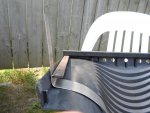
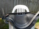
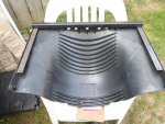
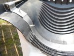
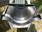
I used a lawn chair to hold/support the plastic cover during assembly
(it just didn't sit on a workbench too well) :ack2:

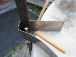
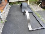
First, I bolted the side rails to the rear bar
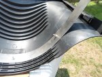
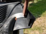
...then, began forming the "hoop" strap to fit nice-n-tight inside of the "scoop"

It looked like a "formed" end would be the best way to come around-n-connect with the sides
…& for added strength, I brought the extra material on around to meet back up with the "hoop" again :cheers2:

I evenly spread out some 1/4" nuts-n-bolts to attach the sub frame
…& kinda giv'er some "bling" :2guns:
 

Attachments

  • SAM_2189.jpg
    SAM_2189.jpg
    273 KB · Views: 1
  • SAM_2187.jpg
    SAM_2187.jpg
    341 KB · Views: 1
  • SAM_2185.jpg
    SAM_2185.jpg
    263.4 KB · Views: 1
  • SAM_2184.jpg
    SAM_2184.jpg
    319.6 KB · Views: 1
  • SAM_2181.jpg
    SAM_2181.jpg
    333 KB · Views: 1
  • SAM_2193.jpg
    SAM_2193.jpg
    293.6 KB · Views: 1
  • SAM_2191.jpg
    SAM_2191.jpg
    410.1 KB · Views: 1
  • SAM_2194.jpg
    SAM_2194.jpg
    362.9 KB · Views: 1
  • SAM_2197.jpg
    SAM_2197.jpg
    249 KB · Views: 1
  • SAM_2199.jpg
    SAM_2199.jpg
    376.1 KB · Views: 1

Functional Artist

Well-known member
Messages
5,599
Reaction score
3,203
Location
Toledo, Ohio
That seemed to come out pretty good :thumbsup:

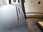
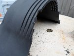
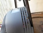
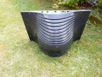
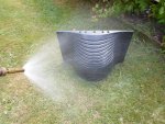
Then, I took 'er all apart, for some smoothin', cleanin' & paintin' :cheers2:

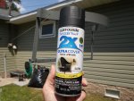
I sprayed the subframe with just some, spray can, satan black
…& while that was dryin', I scrubbed the plastic "shell" with some dish soap :2guns:
 

Attachments

  • SAM_2217.jpg
    SAM_2217.jpg
    284.3 KB · Views: 2
  • SAM_2216.jpg
    SAM_2216.jpg
    294.9 KB · Views: 2
  • SAM_2213.jpg
    SAM_2213.jpg
    302.9 KB · Views: 2
  • SAM_2210.jpg
    SAM_2210.jpg
    374.3 KB · Views: 2
  • SAM_2212.jpg
    SAM_2212.jpg
    353 KB · Views: 2
  • SAM_2224.jpg
    SAM_2224.jpg
    653.3 KB · Views: 5
  • SAM_2223.jpg
    SAM_2223.jpg
    535.5 KB · Views: 2
  • SAM_2221.jpg
    SAM_2221.jpg
    722.5 KB · Views: 3
  • SAM_2229.jpg
    SAM_2229.jpg
    268.2 KB · Views: 2
  • SAM_2219.jpg
    SAM_2219.jpg
    275.3 KB · Views: 2

Functional Artist

Well-known member
Messages
5,599
Reaction score
3,203
Location
Toledo, Ohio
While all of that's dryin', how about them ribs? :huh:

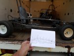
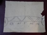
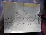
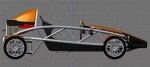
To kinda duplicate the Aerial Atom look we need to/should add some "ribs" to the "rib rails" :thumbsup:

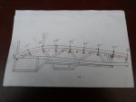
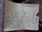
They usually have (5) "ribs" (like the diagram shows)
...but, this seems a bit much
(I'm thinkin' (maybe) we can/should reduce this down a bit) :idea2:

The actual car is
...a lot larger (so, there is a lot further distance between contact points)
…& it's also made of thinner materials (so, understandably it would/should have more bracing)

Another thing, I think the front or first "rib" should be/go from the top-to-the-bottom
...to help brace & strengthen the shock area :cheers2:
...NOT from the bottom-to-the-top, as shown in the diagram :ack2:

Then, maybe only (2) or (3) other "ribs"
...but, still tryin' to incorporate the ~45* triangles
...to help maintain the look :2guns:

I'm kinda likin' the (3) "rib" style
…& it would only need (6) bars, (12) notches, (12) welds & only (12) spatters to clean up :2guns:

Where as the (5) "rib" style would need
...(10) bars, (20) notches, (20) welds & there would be (20) spatters to clean up :smiley_omg:

Whadda ya'all think?
 

Attachments

  • SAM_2239.jpg
    SAM_2239.jpg
    274.3 KB · Views: 2
  • SAM_2238.jpg
    SAM_2238.jpg
    181.6 KB · Views: 2
  • SAM_2241.jpg
    SAM_2241.jpg
    367.9 KB · Views: 2
  • SAM_2242.jpg
    SAM_2242.jpg
    345.8 KB · Views: 4
  • SAM_2243.jpg
    SAM_2243.jpg
    393.5 KB · Views: 4
  • SAM_2249.jpg
    SAM_2249.jpg
    429.5 KB · Views: 5
  • SAM_2248.jpg
    SAM_2248.jpg
    355.8 KB · Views: 3
  • SAM_2246.jpg
    SAM_2246.jpg
    338.8 KB · Views: 4
  • SAM_2245.jpg
    SAM_2245.jpg
    387 KB · Views: 3

Functional Artist

Well-known member
Messages
5,599
Reaction score
3,203
Location
Toledo, Ohio
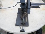
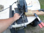
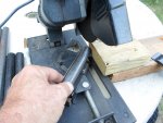
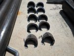
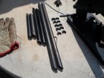
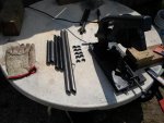
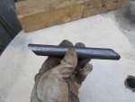
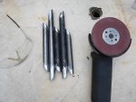
Hmmm, OK so, I set the cutter up to cut ~45* angles
…& went ahead & cut the ends off of a bunch of various lengths of pipe
(so, I could do some "more exact" test fittin') :thumbsup:

I also set up a "stop" or a "jig" (I guess you would call it)
...to but each pipe up to for cuttin'
(so, they will all have the same cut in the same area) :cheers2:

* I set 'er up to leave a bit of the end of the pipe
...for better/easier notching

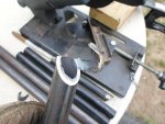
Then, I cut the other end off
...180* from the first cut :2guns:

** Had a kool row of scraps in the end :lolgoku:
 

Attachments

  • SAM_2251.jpg
    SAM_2251.jpg
    278.7 KB · Views: 2
  • SAM_2255.jpg
    SAM_2255.jpg
    321.1 KB · Views: 2
  • SAM_2254.jpg
    SAM_2254.jpg
    273.8 KB · Views: 2
  • SAM_2263.jpg
    SAM_2263.jpg
    224.2 KB · Views: 3
  • SAM_2264.jpg
    SAM_2264.jpg
    178.6 KB · Views: 3
  • SAM_2268.jpg
    SAM_2268.jpg
    383.7 KB · Views: 4
  • SAM_2267.jpg
    SAM_2267.jpg
    322.1 KB · Views: 3
  • SAM_2266.jpg
    SAM_2266.jpg
    288.8 KB · Views: 3
  • SAM_2265.jpg
    SAM_2265.jpg
    243.5 KB · Views: 2

Functional Artist

Well-known member
Messages
5,599
Reaction score
3,203
Location
Toledo, Ohio
Yea (3) looks kool
...but, it seems like that's just gettin' a little too far away from the look of an Atom
...& my dad always told me "if your gonna do something, ya might as well do it right!" :thumbsup:

So, I went back to the drawin' board :idea2:
…& tried a few different variations with (4) "ribs"
…& also a few variations with (5) "ribs"

Well, I'ma gonna go with the (5) "ribs" :wai:
…with just (4) it always looked like there was something missing :huh:

Then, I started "fine tuning" the notches
...to help 'em fit nice-n-snug :2guns:
 

Attachments

  • SAM_2271.jpg
    SAM_2271.jpg
    440 KB · Views: 2
  • SAM_2274.jpg
    SAM_2274.jpg
    353.9 KB · Views: 4
  • SAM_2281.jpg
    SAM_2281.jpg
    377.7 KB · Views: 4
  • SAM_2285.jpg
    SAM_2285.jpg
    239.2 KB · Views: 3
  • SAM_2314.jpg
    SAM_2314.jpg
    369.2 KB · Views: 3
  • SAM_2313.jpg
    SAM_2313.jpg
    343.4 KB · Views: 3
  • SAM_2312.jpg
    SAM_2312.jpg
    348.7 KB · Views: 2
  • SAM_2311.jpg
    SAM_2311.jpg
    384.9 KB · Views: 2
  • SAM_2310.jpg
    SAM_2310.jpg
    314.4 KB · Views: 3
  • th74R2UUSO.jpg
    th74R2UUSO.jpg
    8 KB · Views: 48

Functional Artist

Well-known member
Messages
5,599
Reaction score
3,203
Location
Toledo, Ohio
I "tacked" 'em in place @ first
...just to check :thumbsup:

Yup, looks good to me :cheers2:

Then, welded 'em on good :2guns:

(used my "splatter blocker" to help protect stuff, while welding)
 

Attachments

  • SAM_2321.jpg
    SAM_2321.jpg
    428.6 KB · Views: 0
  • SAM_2322.jpg
    SAM_2322.jpg
    372.3 KB · Views: 3
  • SAM_2320.jpg
    SAM_2320.jpg
    393.3 KB · Views: 2
  • SAM_2317.jpg
    SAM_2317.jpg
    392.2 KB · Views: 2
  • SAM_2316.jpg
    SAM_2316.jpg
    370.3 KB · Views: 1
  • SAM_2323.jpg
    SAM_2323.jpg
    375.1 KB · Views: 0
  • SAM_2327.jpg
    SAM_2327.jpg
    435 KB · Views: 1
  • SAM_2331.jpg
    SAM_2331.jpg
    518.9 KB · Views: 1
  • SAM_2332.jpg
    SAM_2332.jpg
    461.7 KB · Views: 1
  • SAM_2333.jpg
    SAM_2333.jpg
    547.5 KB · Views: 0

Functional Artist

Well-known member
Messages
5,599
Reaction score
3,203
Location
Toledo, Ohio
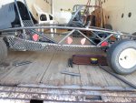
Now we gotta, make the other side match :thumbsup:
...but, that's easier said than done :huh:

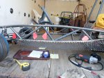
First, I cut (5) "ribs", same as the left side
…& tried, to do a dry fit
...but, where do they go?

Yup, gotta do some measurin' & markin'

Measurin'
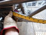
I did the top rail first, started measurin' at the seat "side brace" bar
...recording the data as I went along
(so, I would have a nice even starting point to work with)
…& then, did the lower rail, startin' at where it meets the "motor box"

Markin
Then, marked those coordinates on the right side :cheers2:
 

Attachments

  • SAM_2353.jpg
    SAM_2353.jpg
    220.6 KB · Views: 0
  • SAM_2351.jpg
    SAM_2351.jpg
    423.7 KB · Views: 0
  • SAM_2355.jpg
    SAM_2355.jpg
    450 KB · Views: 0
  • SAM_2359.jpg
    SAM_2359.jpg
    317.6 KB · Views: 0
  • SAM_2360.jpg
    SAM_2360.jpg
    336.3 KB · Views: 0
  • SAM_2363.jpg
    SAM_2363.jpg
    276.1 KB · Views: 0
  • SAM_2378.jpg
    SAM_2378.jpg
    292.3 KB · Views: 0
  • SAM_2376.jpg
    SAM_2376.jpg
    309.4 KB · Views: 0
  • SAM_2377.jpg
    SAM_2377.jpg
    357.3 KB · Views: 0
  • SAM_2374.jpg
    SAM_2374.jpg
    283.9 KB · Views: 1

Functional Artist

Well-known member
Messages
5,599
Reaction score
3,203
Location
Toledo, Ohio
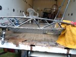
Now that we know where to put the "ribs" :thumbsup:
…& have 'em fitted pretty well

We gotta get everything cleaned up, for weldin' :cheers2:

I put the alignment marks high/low as to not remove them during the clean up
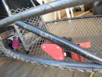
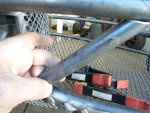
…& used the "splatter blocker" to protect the tires/suspension while weldin'

Then, tacked 'em in place :2guns:
 

Attachments

  • SAM_2386.jpg
    SAM_2386.jpg
    415.6 KB · Views: 2
  • SAM_2385.jpg
    SAM_2385.jpg
    396.1 KB · Views: 1
  • SAM_2383.jpg
    SAM_2383.jpg
    267.8 KB · Views: 1
  • SAM_2381.jpg
    SAM_2381.jpg
    456.9 KB · Views: 1
  • SAM_2379.jpg
    SAM_2379.jpg
    322.6 KB · Views: 1

Functional Artist

Well-known member
Messages
5,599
Reaction score
3,203
Location
Toledo, Ohio
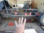
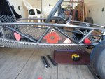
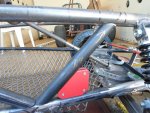
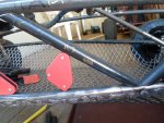
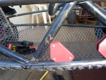
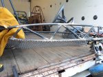
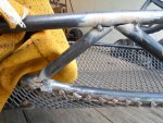
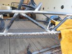
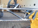
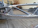
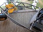
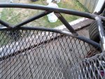
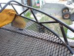
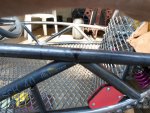
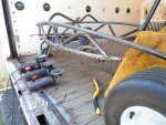
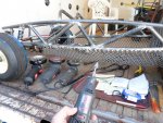
Lookin' thru from the sides & down from the top
...them "ribs" seem to line up pretty goodly :thumbsup:

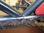
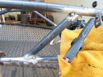
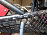
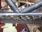
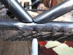
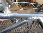
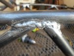
After weldin', we gotta do lots of clean-up :huh:

Mainly wanted to get rid of the flux, splatter & smooth 'em a bit
...but, keep the kinda rough industrial look :cheers2:

I kinda over did it in the last pic :ack2:
...don't know what I was thinkin'...?

Maybe I'll re-weld it so, it'll match :2guns:

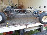
* Yup, whole kart built with HF 90A flux core welder
…& 1/2" schedule 40 water pipe

** Clean up (all welds)
1) wire brush (removes most of the flux)
2) hand scraper (removes most of the splatter balls)
3) wire wheel (smooths & deburrs)
4) rough wheel (to remove high spots/unwanted material)
5) 80 grit sand pad (mainly-to clean up the "rough grinder" marks)
6) die grinder (to get into the tight spots/nooks-n-crannies)
 

Attachments

  • SAM_2396.jpg
    SAM_2396.jpg
    480.5 KB · Views: 4
  • SAM_2398.jpg
    SAM_2398.jpg
    392.1 KB · Views: 4
  • SAM_2404.jpg
    SAM_2404.jpg
    407.4 KB · Views: 4
  • SAM_2410.jpg
    SAM_2410.jpg
    359.1 KB · Views: 4
  • SAM_2411.jpg
    SAM_2411.jpg
    203.2 KB · Views: 4
  • SAM_2412.jpg
    SAM_2412.jpg
    270.5 KB · Views: 4
Top