Building a go kart size Aerial Atom

Functional Artist

Well-known member
Messages
4,411
Reaction score
1,694
Location
Toledo, Ohio
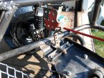
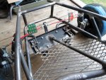
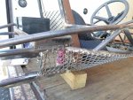
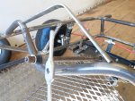
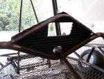
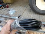
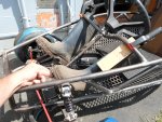
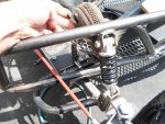
My foot pedal throttle doesn't seem to fit in this situation too well :huh:

So, maybe we'll try some standard go kart type pedals :thumbsup:

But, how are we gonna get 'em mounted?
...don't want to drill holes in the frame (to weaken it)
…& don't want to weld 'em on (difficult to adjust or change your mind)

:idea2: 
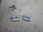
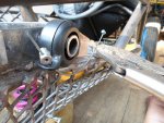
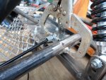
Maybe we can make some mounts that will bolt on
...using existing bolts/holes :cheers2:

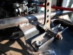
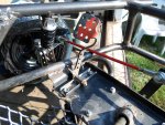
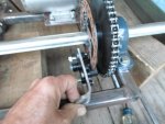
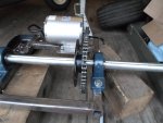
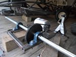
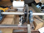
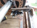
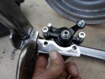
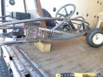
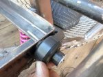
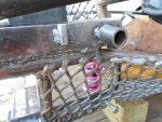
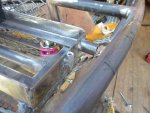
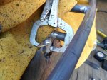
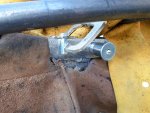
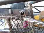
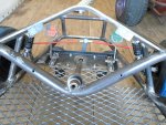
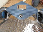
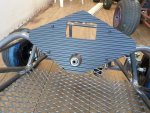
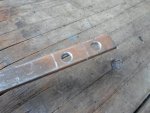
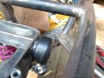
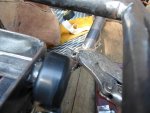
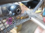
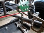
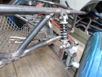
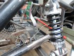
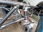
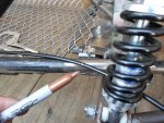
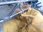
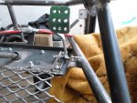
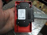
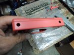
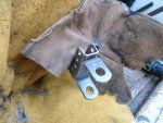
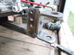
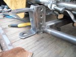
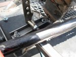
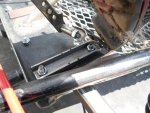
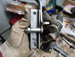
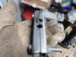
So, I made a couple of brackets that will mount to the suspension bolts
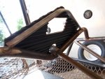
…then, marked where the pedal pivot needs to be welded on

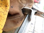
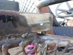
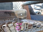
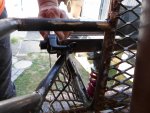
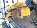
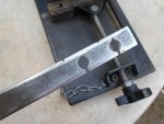
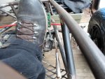
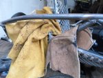
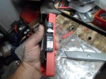
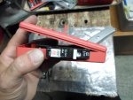
* I couldn't get accurate measurements, while sitting in the seat
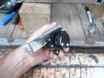
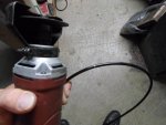
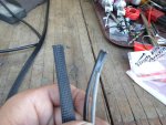
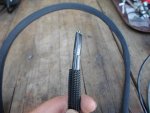
...so, I used some old rubber boots for sizing/positioning of them pedals

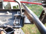
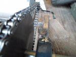
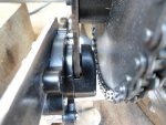
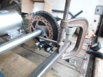
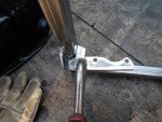
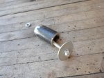
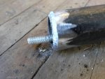
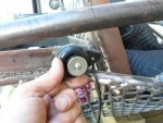
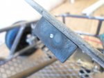
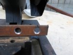
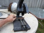
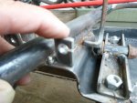
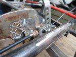
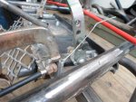
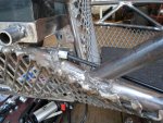
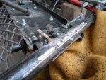
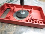
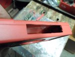
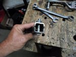
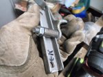
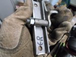
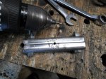
To make "even" low spots on each mount, for the pivot pipe, I first bolted 'em together
...drilled a pilot hole
…& then, drilled 'em out, up to 3/8"

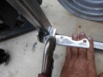
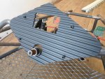
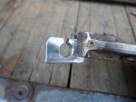
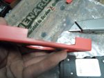
So then, when I took 'em apart
...the pivot pipes fit nicely :cool:
 

Attachments

  • SAM_2418.jpg
    SAM_2418.jpg
    418.5 KB · Views: 2
  • SAM_2419.jpg
    SAM_2419.jpg
    392.8 KB · Views: 3
  • SAM_2420.jpg
    SAM_2420.jpg
    302.6 KB · Views: 2
  • SAM_2421.jpg
    SAM_2421.jpg
    326.8 KB · Views: 2
  • SAM_2422.jpg
    SAM_2422.jpg
    297.3 KB · Views: 2
  • SAM_2433.jpg
    SAM_2433.jpg
    267.8 KB · Views: 2
  • SAM_2434.jpg
    SAM_2434.jpg
    295.1 KB · Views: 2
  • SAM_2432.jpg
    SAM_2432.jpg
    312 KB · Views: 2
  • SAM_2431.jpg
    SAM_2431.jpg
    330.8 KB · Views: 1
  • SAM_2424.jpg
    SAM_2424.jpg
    357.1 KB · Views: 1

Functional Artist

Well-known member
Messages
4,411
Reaction score
1,694
Location
Toledo, Ohio
A little "metal fusin'"
…& (2) become (1) :smiley_omg:

They seem to be "good-n-solid"
...clear the frame rails well
…& the "stops" even interact with the base nicely :cheers2:

I tried switchin' 'em the other way (last pic)
...just to see


Yea, that won't confuse anyone :rolleyes:
...red means go
...green means stop :lolgoku:
 

Attachments

  • SAM_2439.jpg
    SAM_2439.jpg
    329.5 KB · Views: 4
  • SAM_2440.jpg
    SAM_2440.jpg
    349.3 KB · Views: 4
  • SAM_2437.jpg
    SAM_2437.jpg
    423.7 KB · Views: 2
  • SAM_2438.jpg
    SAM_2438.jpg
    451.9 KB · Views: 3
  • SAM_2435.jpg
    SAM_2435.jpg
    420.7 KB · Views: 3

Functional Artist

Well-known member
Messages
4,411
Reaction score
1,694
Location
Toledo, Ohio
Now that we have pedal's, what we gonna hook 'em to? :huh:

The accelerator pedal needs to be connected to a Hall Effect type throttle
…& the brake petal, to the caliper

We should be able to use a thumb type throttle, actuated by a cable
…& the caliper will be cable actuated too.

Not exactly sure where to put the thumb throttle
...but, the caliper needs to be mounted in a pretty specific region (we'll work on that first) :thumbsup:

So, I removed the swing arm
...then, mounted the axle/bearings/sprocket & rotor assembly
...mounted the motor
…& measured/cut/installed & adjusted the chain

Now that we know exactly where the rotor will reside, we can work on makin' a caliper mount.

I initially wanted to use/make a mount that would span from the square tube in front of the axle, to the tube behind the axle
...but, the angle that the caliper needed to be, to interact with the rotor, just wouldn't work out :ack2:

So, I make a mount that only mounted to the rear tube
...just gotta make sure it's good-n-secure :cheers2:

I also initially wanted to weld it to the inside edge of the tube
...but, the angle thing got in the way again

Mounted on top of the tube seemed to work out well so, I figured that I'd add a "hook" to the rear/mounting end of the bracket (for some additional support) :2guns:

Then, I clamped 'er down
...double checking the alignment (brake pads to rotor) side to side
…& also makin' sure the rotor was fully into the caliper, while not actually touching (caliper to rotor) on either end

Then, when I spun the axle/rotor, to triple check alignment
…& found that the rotor is warped just a bit :smiley_omg:

It still seemed to work within the "parameters"
...we'll just have to see if it can be felt while driving

Covered everything with the splatter blocker & tacked 'er down

Yup, it seems to work fine
…& clear the sprocket/chain nicely too :wai:
 

Attachments

  • SAM_2452.jpg
    SAM_2452.jpg
    257 KB · Views: 4
  • SAM_2447.jpg
    SAM_2447.jpg
    323.6 KB · Views: 3
  • SAM_2445.jpg
    SAM_2445.jpg
    260 KB · Views: 4
  • SAM_2446.jpg
    SAM_2446.jpg
    287 KB · Views: 6
  • SAM_2444.jpg
    SAM_2444.jpg
    293.1 KB · Views: 3
  • SAM_2461.jpg
    SAM_2461.jpg
    234.6 KB · Views: 5
  • SAM_2458.jpg
    SAM_2458.jpg
    355.9 KB · Views: 6
  • SAM_2457.jpg
    SAM_2457.jpg
    295.3 KB · Views: 3
  • SAM_2455.jpg
    SAM_2455.jpg
    393.1 KB · Views: 3
  • SAM_2453.jpg
    SAM_2453.jpg
    291.3 KB · Views: 3

Functional Artist

Well-known member
Messages
4,411
Reaction score
1,694
Location
Toledo, Ohio
After weldin' 'er on, I was thinkin' that we have a nice 2D connection
...but, a 3D connection would be even better :thumbsup:

So, I added another small piece of 1/8" steel
...that tags the caliper bracket to the swing arm (from another direction) :cheers2:
 

Attachments

  • SAM_2504.jpg
    SAM_2504.jpg
    313.9 KB · Views: 2
  • SAM_2506.jpg
    SAM_2506.jpg
    282.7 KB · Views: 2
  • SAM_2507.jpg
    SAM_2507.jpg
    382.2 KB · Views: 2

Functional Artist

Well-known member
Messages
4,411
Reaction score
1,694
Location
Toledo, Ohio
Now for the thumb throttle :thumbsup:

The cord/wire on it is ~36" long & being "cable actuated", it can go just about anywhere
...but, it's made of plastic & has moving parts, so we gotta keep that in mind too :cheers2:

At first I thought/tried a few places up/near the throttle pedal
...but, couldn't find a suitable spot that couldn't/wouldn't get accidentally "kicked" &/or pelted by rocks/debris from the front tire :ack2:

Lookin' around in the rear area, it's startin' to get kinda tight back there with the motor, sprocket/rotor/chain/axle & shock/springs all "movin'/bouncin' around" :smiley_omg:

But, I think I found a "safe spot" :wai:
...kinda right up/under the right arm pit, on the side of the battery box :cool:
(the wire/core even "nice-n-safely" wraps around the battery box in/toward the center of the kart)

So, I drilled a hole to temporarily secure the thumb throttle "post", for "test fittin" & then welding
…& used a nut, bolt & washer to "bolt 'er down
...then, beveled the bottom edge of the "post" in an effort to keep the welding "build up" to a minimum
(to keep 'er in the gap)

Yup, that seems to work nicely :2guns:
 

Attachments

  • SAM_2470.jpg
    SAM_2470.jpg
    297.5 KB · Views: 4
  • SAM_2469.jpg
    SAM_2469.jpg
    323.9 KB · Views: 4
  • SAM_2468.jpg
    SAM_2468.jpg
    326.7 KB · Views: 4
  • SAM_2467.jpg
    SAM_2467.jpg
    392 KB · Views: 4
  • SAM_2466.jpg
    SAM_2466.jpg
    391.1 KB · Views: 7
  • SAM_2473.jpg
    SAM_2473.jpg
    319.1 KB · Views: 3
  • SAM_2474.jpg
    SAM_2474.jpg
    251.9 KB · Views: 4
  • SAM_2476.jpg
    SAM_2476.jpg
    278.1 KB · Views: 3
  • SAM_2475.jpg
    SAM_2475.jpg
    307.5 KB · Views: 4
  • SAM_2477.jpg
    SAM_2477.jpg
    336.8 KB · Views: 4

Functional Artist

Well-known member
Messages
4,411
Reaction score
1,694
Location
Toledo, Ohio
I kept my HF 90A welder set on "high"
...but, in an effort to keep the "build up" down to a minimum, I turned the speed setting down to ~3
(so, it would not put out as much material) :thumbsup:

Before weldin', I covered everything with the "splatter blocker" :cheers2:

* While I was there I went ahead & clamped down & welded on a couple of "tall" 1/4" nuts
...to use for/with the battery hold down bracket. :2guns:
…& used an old Chevy Valve Cover "washer" to help keep em' level :idea2:
 

Attachments

  • SAM_2484.jpg
    SAM_2484.jpg
    311.3 KB · Views: 2
  • SAM_2483.jpg
    SAM_2483.jpg
    296.2 KB · Views: 1
  • SAM_2482.jpg
    SAM_2482.jpg
    353.4 KB · Views: 1
  • SAM_2481.jpg
    SAM_2481.jpg
    444.2 KB · Views: 1
  • SAM_2480.jpg
    SAM_2480.jpg
    378.1 KB · Views: 1
  • SAM_2485.jpg
    SAM_2485.jpg
    347.5 KB · Views: 3

Functional Artist

Well-known member
Messages
4,411
Reaction score
1,694
Location
Toledo, Ohio
I ordered some cables to connect the brake & throttle :thumbsup:

While waitin' on them, I started thinkin' about the "forward controls"
...that would be a switch for the "power lock" on/off, the "Astern" reverse control & the dashboard :cheers2:

* I'm gonna mount the 3-speed selector switch into the rear connection box

This way it will be easily "parent" accessible
...but, not up front to be confused with other controls :cheers2:

There's a little bit of room on the dash board
...but, I was thinkin, maybe we can mount the switches right into the steering wheel

This way they will be easily "operator" accessible
…while helping to keep the dash simple

Speakin' of the dash board, we gotta add some bracin'
...as of now, it is just a piece of plastic, that mounts to the dash bar

So, I rounded up a piece of 1/8" x 1/2" steel
…& added a custom bend
...then, welded 'er on

Drilled & tapped a couple of "lower" mounting holes
...then, welded on some "tabs" to drill & tap for "upper" bolt holes

That look's pretty-good-n-solid
...& there's still plenty of room, if we need to add a switch or something :2guns:
 

Attachments

  • SAM_2522.jpg
    SAM_2522.jpg
    362 KB · Views: 2
  • SAM_2516.jpg
    SAM_2516.jpg
    309.5 KB · Views: 2
  • SAM_2519.jpg
    SAM_2519.jpg
    290.4 KB · Views: 2
  • SAM_2518.jpg
    SAM_2518.jpg
    377.3 KB · Views: 2
  • SAM_2525.jpg
    SAM_2525.jpg
    167.8 KB · Views: 2
  • SAM_2526.jpg
    SAM_2526.jpg
    395.3 KB · Views: 2
  • SAM_2527.jpg
    SAM_2527.jpg
    314.1 KB · Views: 2
  • SAM_2528.jpg
    SAM_2528.jpg
    380.5 KB · Views: 2

Functional Artist

Well-known member
Messages
4,411
Reaction score
1,694
Location
Toledo, Ohio
Need to make some cable housing/mounting brackets (nuthin' fancy but, they gotta be strong) :thumbsup:
…(2) for the throttle cable, (1) for each end
…& just (1) for the front/pedal end of the brake cable

So, I marked (2) pieces of 1/8" x 1/2" steel @ ~3/4" long
...drilled a couple of holes
...cut some cable "slots"
...made some cut notches (before cleaning & removing my cut marks)
...cleaned 'em up
...cut 'em apart
...& then, rounded the top edges off a bit :cheers2:

* I've found that it's easier to "grip" & to work on, small stuff, while it's still is/attached to a bigger piece :idea2:

Can't see in the pics too well
...but, this is how the thumb throttle looks
...this is where the bracket will mount
…& this is where/how the cable should/will travel thru that bracket

Then the cable can/will follow the frame rail up toward the pedal :2guns:
 

Attachments

  • SAM_2497.jpg
    SAM_2497.jpg
    387.5 KB · Views: 2
  • SAM_2494.jpg
    SAM_2494.jpg
    222.5 KB · Views: 2
  • SAM_2489.jpg
    SAM_2489.jpg
    204.8 KB · Views: 2
  • SAM_2488.jpg
    SAM_2488.jpg
    307.6 KB · Views: 2
  • SAM_2487.jpg
    SAM_2487.jpg
    325.1 KB · Views: 2
  • SAM_2498.jpg
    SAM_2498.jpg
    195.1 KB · Views: 2
  • SAM_2502.jpg
    SAM_2502.jpg
    321.5 KB · Views: 2
  • SAM_2503.jpg
    SAM_2503.jpg
    280.3 KB · Views: 2
  • SAM_2500.jpg
    SAM_2500.jpg
    260.9 KB · Views: 1
  • SAM_2501.jpg
    SAM_2501.jpg
    268.5 KB · Views: 1

Functional Artist

Well-known member
Messages
4,411
Reaction score
1,694
Location
Toledo, Ohio
Workin' on/figurin' where to put the front cable mount/brackets :idea2:
I was thinkin' to just put 'em down on the "flat plate" where the pedal mounts bolt down?(see pics)
...but, I noticed that for the cable to intersect/connect with/to the pedal, the cable angle seems like it would be a little too steep :ack2:

Then, I was thinkin' maybe, mount them up a bit higher, on the lower frame rail? (angled in just a bit)

This way seems to "line up" better
…& give us the option to use higher connection points on the pedals (if necessary) :cheers2:

* Either way they should still be "out of harms way" :2guns:
 

Attachments

  • SAM_2654.jpg
    SAM_2654.jpg
    236.7 KB · Views: 1
  • SAM_2655.jpg
    SAM_2655.jpg
    358 KB · Views: 1
  • SAM_2648.jpg
    SAM_2648.jpg
    367.2 KB · Views: 1
  • SAM_2652.jpg
    SAM_2652.jpg
    277.1 KB · Views: 1
  • SAM_2650.jpg
    SAM_2650.jpg
    287.3 KB · Views: 1
  • SAM_2656.jpg
    SAM_2656.jpg
    395.8 KB · Views: 1
  • SAM_2657.jpg
    SAM_2657.jpg
    282.1 KB · Views: 2
  • SAM_2658.jpg
    SAM_2658.jpg
    337.5 KB · Views: 2
  • SAM_2659.jpg
    SAM_2659.jpg
    290.3 KB · Views: 2
  • SAM_2660.jpg
    SAM_2660.jpg
    339.3 KB · Views: 2

Functional Artist

Well-known member
Messages
4,411
Reaction score
1,694
Location
Toledo, Ohio
I got a 50" roll of throttle/brake cable housing from BMI for ~$10.00
(should last a minute)

So, starting at the "tacked on" rear throttle cable mounting "tab",
...inserted a cable end
...& also, the end of the cable housing

Then, ran the cable housing along the lower "rib rail" up to the area where the front "tab" should mount
...& marked it for cutting. (gold on black)

The HF "cut off tool" easily & cleanly sliced right thru it :thumbsup:

After double checkin'
...how the cable would "line up" &/or interact with both the throttle & pedal attachment points
...I clamped the tab in place for welding

Checked everything a third (& final) time
...covered everything with the "splatter blocker"
...& welder 'er on good :cheers2:

* While I was at it, I welded the rear throttle cable "tab" on good
...& the one on the left front, for mounting the brake cable too :2guns:
 

Attachments

  • SAM_2682.jpg
    SAM_2682.jpg
    207.2 KB · Views: 3
  • SAM_2678.jpg
    SAM_2678.jpg
    265.2 KB · Views: 2
  • SAM_2677.jpg
    SAM_2677.jpg
    349.3 KB · Views: 2
  • SAM_2674.jpg
    SAM_2674.jpg
    380.1 KB · Views: 2
  • SAM_2672.jpg
    SAM_2672.jpg
    297.5 KB · Views: 3
  • SAM_2731.jpg
    SAM_2731.jpg
    294.1 KB · Views: 3
  • SAM_2733.jpg
    SAM_2733.jpg
    350 KB · Views: 3
  • SAM_2734.jpg
    SAM_2734.jpg
    299.8 KB · Views: 4
  • SAM_2735.jpg
    SAM_2735.jpg
    329.7 KB · Views: 4
  • SAM_2737.jpg
    SAM_2737.jpg
    335.7 KB · Views: 3

Functional Artist

Well-known member
Messages
4,411
Reaction score
1,694
Location
Toledo, Ohio
3-speed switch

Still gotta a lot of "clean up" to do on the "main frame" :huh:
...but, let's take a break on that for a minute & work on the wiring a bit :thumbsup:

First, I cut a hole & mounted the 3-speed switch, into the side of the connection box
…cut the plug off
...& crimped spade terminals onto each of the wires

Then, I simply slid/plugged each one of them onto the terminals of the switch :cheers2:
 

Attachments

  • SAM_2529.jpg
    SAM_2529.jpg
    181.4 KB · Views: 3
  • SAM_2531.jpg
    SAM_2531.jpg
    275.6 KB · Views: 3
  • SAM_2532.jpg
    SAM_2532.jpg
    293.9 KB · Views: 3
  • SAM_2533.jpg
    SAM_2533.jpg
    269.3 KB · Views: 3
  • SAM_2537.jpg
    SAM_2537.jpg
    162.4 KB · Views: 3
  • SAM_2610.jpg
    SAM_2610.jpg
    226.9 KB · Views: 2
  • SAM_2609.jpg
    SAM_2609.jpg
    260 KB · Views: 2
  • SAM_2540.jpg
    SAM_2540.jpg
    203.7 KB · Views: 2
  • SAM_2538.jpg
    SAM_2538.jpg
    257.7 KB · Views: 2

Functional Artist

Well-known member
Messages
4,411
Reaction score
1,694
Location
Toledo, Ohio
We need to make a wiring harness to bring (some of) the necessary wires up to the front. :thumbsup:

So, I used (2) ~4' pieces of 22-4 wire
(4 individual 22g. wires red, black, green & white, in a single outer cover)
...(1) piece for the logic wires
...(1) piece for the meter wires

I shot a little mist of black paint on the outer cover, of the (1) for the logic wires, to be able to tell them apart
…& then, ran them both thru a nylon covering, for extra protection :cheers2:

Then, I installed (2) plugs on each end of the "logic cable"
…(1) plug will connect the on/off switch to the "power lock" plug, on the controller
...& the other will connect the reverse switch to the "Astern" plug, on the controller

For the "meter cable", I installed ring terminals on the "connection box" end
...to connect the signal wires (B- & P-) to the shunt
...& also a bullet terminal to connect the (B+) to the "Voltage indicator" plug, on the controller
...there are screw tabs that make for "easy connections" on the meter end :cool:
 

Attachments

  • SAM_2541.jpg
    SAM_2541.jpg
    180.5 KB · Views: 4
  • SAM_2597.jpg
    SAM_2597.jpg
    342.6 KB · Views: 4
  • SAM_2599.jpg
    SAM_2599.jpg
    212.5 KB · Views: 2
  • SAM_2600.jpg
    SAM_2600.jpg
    339.9 KB · Views: 2
  • SAM_2601.jpg
    SAM_2601.jpg
    313 KB · Views: 2
  • SAM_2608.jpg
    SAM_2608.jpg
    242.9 KB · Views: 4
  • SAM_2603.jpg
    SAM_2603.jpg
    235.3 KB · Views: 3
  • SAM_2602.jpg
    SAM_2602.jpg
    219.6 KB · Views: 4
  • SAM_2662.jpg
    SAM_2662.jpg
    219.5 KB · Views: 3
  • SAM_2666.jpg
    SAM_2666.jpg
    217.4 KB · Views: 3

Functional Artist

Well-known member
Messages
4,411
Reaction score
1,694
Location
Toledo, Ohio
Here is the speed controller wiring definitions

60V 2,000W Boma Brushless motor
1.) thick red (+) & thick black (-) = Power/Battery
2.) thick blue, thick yellow, thick green = (power to) Motor
3.) thin red, yellow, green, blue & black = Hall (to Motor)
4.) thin red, orange = Electric Lock (key switch)
5.) thin red (5V), black (GND), green (signal) = Turn The (Throttle)
6.) thin red (+) black (-) (red plug) = Charge (port)
7.) thin orange, white = The Brake
8.) thin white, black = Brake Light
9.) thin orange, black = Indicator Light
10.) thin yellow, black = Astern (for reverse switch)
11.) thin red = Battery Indicator
12.) thin orange, black, blue = 3-speed (switch)

Now that I have all of the controller wires/plugs in the connection box
…& most of the necessary stuff connected (on/off, 3-speed switch, reverse switch, throttle, meter etc.)
...or at least "ready to be connected" :thumbsup:

Next, we need to work on the connections for the battery

To protect our system, I'm gonna (try) a MidNite 150V 50A circuit breaker
(usually used to protect the wiring in Solar Charging Systems)
http://www.midnitesolar.com/product...=Breakers&productCat_ID=16&sortOrder=18&act=p

So, I was thinkin' :idea2: it would be neat, kool & convenient to have the CB mounted on the first battery,
(within reach of the "cock pit")
...but, we need to make a custom enclosure or box :cheers2:

Hmmm
I have a "dead" HF multi-meter
…& maybe the case will work in this situation

Just gotta clean 'er out
…& cut a slot out of the side, for the face/switch of the CB to protrude thru :2guns:
 

Attachments

  • SAM_2543.jpg
    SAM_2543.jpg
    409.3 KB · Views: 3
  • SAM_2550.jpg
    SAM_2550.jpg
    268.6 KB · Views: 2
  • SAM_2549.jpg
    SAM_2549.jpg
    274.1 KB · Views: 2
  • SAM_2548.jpg
    SAM_2548.jpg
    274.2 KB · Views: 3
  • SAM_2547.jpg
    SAM_2547.jpg
    266.6 KB · Views: 2
  • SAM_2545.jpg
    SAM_2545.jpg
    311.4 KB · Views: 2
  • SAM_2559.jpg
    SAM_2559.jpg
    221.4 KB · Views: 2
  • SAM_2564.jpg
    SAM_2564.jpg
    232.2 KB · Views: 2
  • SAM_2566.jpg
    SAM_2566.jpg
    219.4 KB · Views: 3
  • SAM_2567.jpg
    SAM_2567.jpg
    224.1 KB · Views: 2

Functional Artist

Well-known member
Messages
4,411
Reaction score
1,694
Location
Toledo, Ohio
Had to notch out the "cover" just a bit
…& then, drill a couple of holes, for the battery cables

Yup, fits pretty good :thumbsup:

So then, I sat it "in place" on the first battery (I'll secure it down with "industrial Velcro" later)
...& ran the 10g. red positive (+) cable, from the controller "Batt" plug, to the CB "in" (++)
…& added another piece, of red 10g wire, going from the CB "out" to the positive (+) terminal of the battery pack :cheers2:
 

Attachments

  • SAM_2583.jpg
    SAM_2583.jpg
    277.9 KB · Views: 3
  • SAM_2582.jpg
    SAM_2582.jpg
    273.9 KB · Views: 3
  • SAM_2580.jpg
    SAM_2580.jpg
    245.5 KB · Views: 2
  • SAM_2573.jpg
    SAM_2573.jpg
    230.8 KB · Views: 2
  • SAM_2568.jpg
    SAM_2568.jpg
    240.2 KB · Views: 2
  • SAM_2586.jpg
    SAM_2586.jpg
    265.1 KB · Views: 3
  • SAM_2588.jpg
    SAM_2588.jpg
    204.3 KB · Views: 3
  • SAM_2584.jpg
    SAM_2584.jpg
    262.4 KB · Views: 3
  • SAM_2592.jpg
    SAM_2592.jpg
    361.3 KB · Views: 2
  • SAM_2594.jpg
    SAM_2594.jpg
    299.5 KB · Views: 2

Functional Artist

Well-known member
Messages
4,411
Reaction score
1,694
Location
Toledo, Ohio
;)You need to cut up the dial and silicone/glue back on multi meter to cover cb sticker

Yup, the lid/cover goes back on :thumbsup:

I just left if off in the last couple of pics, to show the connections & cable routing. :cheers2:
 

Attachments

  • SAM_2586.jpg
    SAM_2586.jpg
    265.1 KB · Views: 3
  • SAM_2587.jpg
    SAM_2587.jpg
    361.1 KB · Views: 3

Functional Artist

Well-known member
Messages
4,411
Reaction score
1,694
Location
Toledo, Ohio
Tying up some loose ends (here & there) :thumbsup:

Almost forgot, I gotta weld the spindle brackets on

So, first, I made sure the chassis was sittin' level side to side & front to back)

Then, adjusted the brackets to ~85* (leanin' toward the rear of the kart) :cheers2:
...covered most everything with the "splatter blocker"
…& then, applied some kinda heavy duty "tac" welds

*I'm kinda concerned/uncertain about how this "totally custom & experimental" front suspension is gonna function
…& I don't want to weld 'er "on good" just yet
('till I try a few test runs to see how everything's gonna work) :2guns:

(3) tac's per side should be HD enough to test on
...but, not too hard to cut the welds & re-adjust (if necessary) :idea2:
 

Attachments

  • SAM_2742.jpg
    SAM_2742.jpg
    185.2 KB · Views: 3
  • SAM_2746.jpg
    SAM_2746.jpg
    295.9 KB · Views: 3
  • SAM_2748.jpg
    SAM_2748.jpg
    307.1 KB · Views: 4
  • SAM_2749.jpg
    SAM_2749.jpg
    392.4 KB · Views: 4
  • SAM_2751.jpg
    SAM_2751.jpg
    216.7 KB · Views: 5
  • SAM_2752.jpg
    SAM_2752.jpg
    268.8 KB · Views: 4

sikbrik

New member
Messages
131
Reaction score
0
Location
Greater Harrisburg PA area
Good idea hooking up the 3 speed switch...I hard-wired the "fast" setting and a neighbor kid went over a small stone wall and into a small tree... thankfully with a helmet and no real damage done to either the kid or the kart but next season it will have low speed wired up in case my kid lets friends on it again.

It's coming together nicely! Thanks for sharing all the pics and ideas.
 
Top