I know that many of you understand how all of tgese things work but I try to keep in mind the youngsters or folks that might not have aquired this knowledge yet to provide a learning experience for them. I also think about others in the future looking to do something similar might very much appreciate the additional info. Who knows, maybe it will be good enough for a sticky. It would be much easier for me to just do the work and not take the time to share it with others or especially have it there for future reference. I could even just toss the pics up and not provide the reason or theories to the "why" and "how" but then it wouldn't seem complete enough to me that it would help others. So while I am long winded and provide too much gabbing my intention is focused on all the future people that may find it useful.
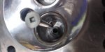
Well I got my carbide in the mail and it wasn't quite what I needed. The tip was too small. So I cut down a cone carbide that I had laying around that has some some wear on the tip to make my own. I worked ok for the purpose. I drilled a hole in the valve bowk roof and sunk a gnarly screw with red locktite in it to providean ample anchor for the epoxy to hang onto. I cut grooves in the port so the epoxy could have more to hang on to as well as drilled and tapped the port and screwed in bolts in several spots to provide an anchoring point for the epoxy. I then added the 2 part steel epoxy to the port and let set to cure for 24hrs. Then I went to town removing material on my first try at making the port shaped the way I think should have a positive effect on velocity, flow and the proper swirl characteristics for good overall performance.
I am trying to maintain proper velocity and air flow in the port to maintain proper fuel atomization, laminar flow, total CFM capable of enough flow during peak torque, create enough swirl in the valve bowl and curtain seat area to produce an even flow of A/F mixture around the valve during decompression while not so much that it throws the fuel out of suspension. I raised the port roof to create a better angle for better laminar flow to the valve seat, raised the port floor to make the short turn much more gradual so the air will flow along the short side easier and into the valve seat area nearest the short side more efficiently which will hopefully prevent it from pulling away and creating valve bowl choke with the long side radius A/F mixture.
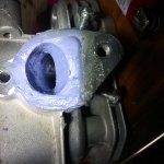
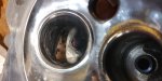
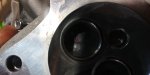
I am not totally happy with the current port shape so I will be going in and reshaping it but I wanted to get going and feel out the port and process to kinda get a feel for the angles and what I want. I biased the port to one side so that more air will flow on one side and then created a stall area in the other in the valve bowl area to stall the air out just a bit to cause a swirl state. I think I will push the stall further up in the bowl towards the valve guide when I redo it. You can see that there is a much longer and more gradual short turn radius also. The valve bowl to valve seat is blended pretty smooth now as well. Before there was a slightly inverted lip.
With the stock port the short turn was very abrupt and short and the long turn opened up to a flat top bowl. I figure that with a more gradual short turn and a long turn with more laminar flow that it should make up for the smaller cross-sectional port area some. The actual amount of CFM needed for this engine is quite small if a fairly efficient flowing port is utilized, which means a port with a fairly small cross-sectional area would provide plenty enough volume needed for even the most demanding point of the rpm and torque curve. So while improving the port flow efficiency you can utilize a smaller port and a tighter cross-sectional area to improve fuel suspension. Improved fuel suspension leads to a more efficient BSFC (Brake Specific Fuel Consumption), which allows for more work to be done with less fuel, again leading to a more efficient engine. On top of that, a smaller, more efficient port is much quicker to respond to valve events making the A/F decompression process start sooner which will start filling the combustion chamber sooner allowing more total charge time to the decompression charge cycle. In addition, during overlap while the exhaust is being scavenged it provides a huge amount of negative pressure. With a more efficient intake port this very brief amount of time of overlap can drastically effect enough change to start a pre-charge cycle where the A/F mixture starts to move before the downward movement of the piston would start to have any effect with the decompression cycle. This tiny bit can make an engine much more responsive and efficient not only at low speed, low and mid valve lift but all the way through the rpm range since the effect is stronger with load and higher speeds. This can create a bump in overall top rpm horsepower as well, dramatically widening and strengthening the torque curve and bumping HP above the curve. These are the things that I am trying to dial in with doing this.
In order to get a better idea of changes made and where I stand compared to stock is to do some testing. The first part of the testing process would to be to utilize an engine head flow bench. While not the most accurate way to determine whether the intake, ports and exhaust is performing better it is a huge step up from the guessing and test running process. It gives you an idea of how well the head flows, total CFM the heads are capable of, port velocities and so on. While it doesn't exactly duplicate an engine while running you can make comparisons between changes you have made in the head and get an idea of what the head will perform like on an engine. So, that's what I think I will do next. I decided to build a flow bench.
Stay tuned.

 17 foot pounds?
")