Exactly, that is why I want a flow bench that will flow almost anything that could come through the door. The classes of Stock cars that these guys race have such tight engine rules that if your not flow checking your engine parts you won't be able to keep up. There rules don't allow them any porting. Instead of using a flow bench to check your porting results, these guys do it for selective parts picking. They will have a couple sets of heads and will be looking for the better castings. Samething with the carburetors. They are allow only a Holley 4412 500cfm carburetor. If you buy one off the shelf (around $450) most likely you won't keep up. Carb builder's sell race prepped and flowed carbs for $800-$1000. You can take 5 of these carbs and only about 3 out of 5 will actually flow what they should. Most flow less and about maybe 1 out of 100 will flow better then rated. So knowing if you have a good casting is the only way to even begin to build a carb. So in conclusion I can see quite a bit of opportunity to make some side cash and is the reason why I want to build one that I know will be easy to operate, consistent,accurate, and able to do what ever comes through the door. Now I just need to get it done!
You are using an out of date browser. It may not display this or other websites correctly.
You should upgrade or use an alternative browser.
You should upgrade or use an alternative browser.
Budget stock 212 Hemi TORQUE MONSTER build!
- Thread starter TheInspiredFool
- Start date
TheInspiredFool
Member
- Messages
- 143
- Reaction score
- 10
Exactly, that is why I want a flow bench that will flow almost anything that could come through the door. The classes of Stock cars that these guys race have such tight engine rules that if your not flow checking your engine parts you won't be able to keep up. There rules don't allow them any porting. Instead of using a flow bench to check your porting results, these guys do it for selective parts picking. They will have a couple sets of heads and will be looking for the better castings. Samething with the carburetors. They are allow only a Holley 4412 500cfm carburetor. If you buy one off the shelf (around $450) most likely you won't keep up. Carb builder's sell race prepped and flowed carbs for $800-$1000. You can take 5 of these carbs and only about 3 out of 5 will actually flow what they should. Most flow less and about maybe 1 out of 100 will flow better then rated. So knowing if you have a good casting is the only way to even begin to build a carb. So in conclusion I can see quite a bit of opportunity to make some side cash and is the reason why I want to build one that I know will be easy to operate, consistent,accurate, and able to do what ever comes through the door. Now I just need to get it done!
Ahh, gotchya. A 500cfm carb is quite the orface to flow steadily and would need to be quite accurate. Well that sounds fun. Them guys sure do spend the money for those magical carbs.
It's kinda sad that if you buy a brand new carb that is used for a class that you won't be competitive in a sanctioned race where the tight rules are there so that it's supposed easy for anyone to be competitive. It seems like it's the same thing as what they are trying to avoid... the people with more money to buy all of the special expensive parts gets a huge advantage and the competitiveness is ruined for the one's who can't afford it.
Your 100% correct! Every time they make a rule on something to try to slow them down or lower the cost it ends up backfiring and the racers spend more time and money to beat the rules. Years ago they had a class with no motor rule other then it had to be factory cast iron parts and one carburetor. The racers spent less money and most of the time guys would have to much motor for the size tire they were on.
TheInspiredFool
Member
- Messages
- 143
- Reaction score
- 10
Your 100% correct! Every time they make a rule on something to try to slow them down or lower the cost it ends up backfiring and the racers spend more time and money to beat the rules. Years ago they had a class with no motor rule other then it had to be factory cast iron parts and one carburetor. The racers spent less money and most of the time guys would have to much motor for the size tire they were on.
Exactly. It's easier for the poor folk to set-up a car to be competitive when it's easy to have too much power. When the engine is the biggest piece you can gain an advantage it gets expensive. With handling and putting the power down to get traction is key it seems that the little guys can be more competitive with less money if they have enough brains. I guess it depends on the track(s) that you race but it seems like there is more money spent with tighter engine rules.
My dad was involved with competitive competition for a big portion of my life and he made a career out of working on other people's equipment to make them more competitive so atleast there is money to be made from the guys willing to dump as much money as it takes to gain as much of an advantage as possible! Lol
TheInspiredFool
Member
- Messages
- 143
- Reaction score
- 10
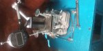
Well I finished the flowbench up finally enough to test it. I had upstream air leaks during my last test-fit phaze totalling about 9-10cfm so I buttoned everything up with silicone which should eliminate the leaks. I quickly tossed the head onto get a quick idea of initial flow and to check for any leaks and found that with the valves closed there was still a very slight vacuum in both the intake and exhaust ports. This points to a valve/valve seat leak even after I lapped the exhaust valve in. I really think the stock exhaust valve seat area is a big problem with these engines. More on this later.
So while I still have to wait for the silicone to finish curing and there was a 10cfm leak I wanted to touch on the intake port numbers so far. I think this port is very responsive and SHOULD work out well. The number started at 10cfm @ -28"H2O and I opened the valve with my finger pressing down the valve with the stock valve spring in place. The cfm jumped to over 50cfm very quickly. I did a slow opening and the number jumped up to over 20cfm very soon in the travel. While this really isn't a very scientific measurement by any means it does give me hope that under proper testing I shouldn't be far off.
My actual reason for doing a quick flow run was actually to listen to the port. I have the shop vac on a variable speed control type device that allows me to adjust the power that the vacuum gets which helps a lot with how loud it is as well as adjusts the amount of vacuum it provides. It works flawlessly. With the power at full tilt the port seemed quiet and smooth sounding. Adjusting the vacuum down it seemed even smoother. The -inH2O and CFM readings were both very stable under both scenarios of vac power. I was actually surprised at how smooth the intake sounded in comparison to the exhaust. In the exhaust you could hear and feel (through the valve tip and body of the head with my fingers) the air becoming turbulent. The intake sounded and felt smooth during the whole movement. While this could turn out to be a bad thing in actual running situations I have hope that I am going in the right direction.
The more experience you have, the more you talk to the true masters of the trick engine building gurus and the more you research these types of things the more you realize that how air/fuel mixtures flows and behaves is usually not how you think it should and that things like flowbench testing and screwing with ports, valve seats, intakes and exhausts is usually more of a lesson in humility than a quick pathway to more power. I accept that I remain a humbled fool and look forward to learning more every day and with each test that I do. I know that flowbench testing (especially dry flowing) is far from an accurate depiction of a depiction of how well an engine will actually run in a real world setting. I can still be creating more problems than I am solving, however, I am excited to see how this will turn out given the introductory tests. I guess time will tell.
Now, about the exhaust valve seat leak. I am convinced that there is a potential for great concern with the sealing (or lack thereof) between the exhaust valve and valve seat. If it had a very small leak after I lapped the exhaust valve I can only surmise that the leak would have been worse and have occurred much more often under load in a running condition. I highly suggest that anyone who is looking to gain more performance to look at the exhaust valve/valve seat condition. You probably know just exactly how well the engine runs and the rpm that it will turn when it starts to float the valve or run out of steam. Check the seal properties, lap the valve in well (properly) and then test how well it runs and the max rpm after lapping the valve in and let me know if you have gained or lost any performance. I can almost guarantee that you will have a slight performance increase as well as gained a little bit in max rpm.
Update: I did the final leakdown test and it showed 0cfm at over -45inH2O so that is perfect. I spent some time on the valves and now there is no leaks in either valve/seat. I am working on the test plate now. I should be up and running soon. I had a bunch of other things come up and had to put this on the side for a bit. I still have otger things going on but am going to try to fit this in when I can.
I think once I get a decent number for the intake I am going to work on the exhaust a bit and just put it on the engine to see how well it runs. I can do wet flow testing this winter to perfect it if I can.
Last edited:
TheInspiredFool
Member
- Messages
- 143
- Reaction score
- 10
Update-Valve movement measuring device done & Flow results
Good question. I only flowed the exhaust like that to get a comparison of sound, reaction speed and flow number. I am actually going to blow air up and out of the exhaust and get a reading that way to base my exhaust flow numbers on. I designed it so I can get a CFM reading in both directions, either blowing or sucking. I'm not sure if any of the big shops do it the same or differently. I will draw through and blow out and compare the readings to be sure that there is more restriction coming in than going out. Same for the intake. I will also do flow tests with the complete intake and exhaust bolted on in both directions for each just to have the data to build up a reference base on what things might have a positive or negative effect. I was also going to add a few remote attachments that could be attached to the exhaust port and header to suck through but I am not sure now. I think the blow through should be ok for now. I am ready to finish this thing up, toss it on the kart and just have it running and useful again.
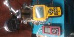
Basically it shows:
64cfn @ .265 lift -28"h2o
46cfm @.100" lift -17"h20
41cfm @ .265" lift -11"h20
Those seem pretty high to me so I want to calibrate it. Stay tuned.
Sorry about the pics being sideways. I will take them in landscape next time. I turned them on my phone before I uploaded them but I think I have to do it in a photo editor.
I would think that shops would turn the head so that they draw through the combustion chamber and out the exhaust but maybe not?
So I put together a quick mounting plate and adjustments to measure the valve travel and tossed the head on. I aligned the needle caliper, pressed in on further than the .263" that the valve would travel, turned the Digital anemometer and digital manometer on. They were both at zero. I turned the vac on and the manometer read -42 in-H2O and the anemometer read zero cfm (no movement of air=no leaks). I eased the screw in until it barely touched the valve lash cap and then zeroed out the digital indicator so that when I turned the screw in I would get a readout of how far the screw has traveled inwards, therefore also telling me how far the valve has opened/traveled.
I am going to have to get a couple of test plates to calibrate the cfm readings because they seem high.
What is funny is that I switched over to the exhaust just to get a comparison. I turned the vac all the way down for both tests. The tightened up intake was 1-2 cfm higher at -17in-H2O @ .100" lift than the exhaust that had been slightly ported over stock. The manometer showed -18 in-H2O but was flowing 1-2cfm less which proves that the port was less efficient because it flowed less cfm as well as the manometer indicating that there was more of a pressure difference. That really surprised me.
I am going to set up the carb as the relief valve just before tge vac so that I can adjust the vacuum down to -10in-H2O. Right now I have it plugged off and am just using the variable controller for the vacuum, which has worked very well and much better than anticipated. If I can get a couple test plates that flow about 20cfm and 50cfm than I can calibrate it very well for the cfm that I will be working with.
Good question. I only flowed the exhaust like that to get a comparison of sound, reaction speed and flow number. I am actually going to blow air up and out of the exhaust and get a reading that way to base my exhaust flow numbers on. I designed it so I can get a CFM reading in both directions, either blowing or sucking. I'm not sure if any of the big shops do it the same or differently. I will draw through and blow out and compare the readings to be sure that there is more restriction coming in than going out. Same for the intake. I will also do flow tests with the complete intake and exhaust bolted on in both directions for each just to have the data to build up a reference base on what things might have a positive or negative effect. I was also going to add a few remote attachments that could be attached to the exhaust port and header to suck through but I am not sure now. I think the blow through should be ok for now. I am ready to finish this thing up, toss it on the kart and just have it running and useful again.
Basically it shows:
64cfn @ .265 lift -28"h2o
46cfm @.100" lift -17"h20
41cfm @ .265" lift -11"h20
Those seem pretty high to me so I want to calibrate it. Stay tuned.
Sorry about the pics being sideways. I will take them in landscape next time. I turned them on my phone before I uploaded them but I think I have to do it in a photo editor.
I would think that shops would turn the head so that they draw through the combustion chamber and out the exhaust but maybe not?
So I put together a quick mounting plate and adjustments to measure the valve travel and tossed the head on. I aligned the needle caliper, pressed in on further than the .263" that the valve would travel, turned the Digital anemometer and digital manometer on. They were both at zero. I turned the vac on and the manometer read -42 in-H2O and the anemometer read zero cfm (no movement of air=no leaks). I eased the screw in until it barely touched the valve lash cap and then zeroed out the digital indicator so that when I turned the screw in I would get a readout of how far the screw has traveled inwards, therefore also telling me how far the valve has opened/traveled.
I am going to have to get a couple of test plates to calibrate the cfm readings because they seem high.
What is funny is that I switched over to the exhaust just to get a comparison. I turned the vac all the way down for both tests. The tightened up intake was 1-2 cfm higher at -17in-H2O @ .100" lift than the exhaust that had been slightly ported over stock. The manometer showed -18 in-H2O but was flowing 1-2cfm less which proves that the port was less efficient because it flowed less cfm as well as the manometer indicating that there was more of a pressure difference. That really surprised me.
I am going to set up the carb as the relief valve just before tge vac so that I can adjust the vacuum down to -10in-H2O. Right now I have it plugged off and am just using the variable controller for the vacuum, which has worked very well and much better than anticipated. If I can get a couple test plates that flow about 20cfm and 50cfm than I can calibrate it very well for the cfm that I will be working with.
Attachments
-
 20200817_013419.jpg3.3 MB · Views: 3
 -
 20200817_014140.jpg3.6 MB · Views: 3
 -
 20200817_014130.jpg3.5 MB · Views: 2
 -
 20200817_013823.jpg2.6 MB · Views: 2
 -
 20200817_013944.jpg3.5 MB · Views: 3
 -
 20200817_014244.jpg3.4 MB · Views: 2
Last edited:
Couple questions. Shouldn't you take all your readings at 28" of water? The Superflow I have access to automatically adjusts the air bleed to 28". The only thing that I have tested different from 28" is carburetors and they are tested at 20.4". For some reason the carb manufacturers use this value. Whats the hole size under the cylinder head? It should be the same or very close to the bore of the engine and there should be a cylinder or chamber at least the length of the stroke or more.
65ShelbyClone
Active member
28" H2O is just the number everyone seems to agree on as a de-facto standard. There's nothing to prevent testing at higher or lower depressions unless the bench simply can't pull enough to maintain the pressure. The pressure goes much lower than -28" in operation and is pulsed flow anyway, so what would the "correct" test depression actually be at constant flow?
Carbs are tested at less depression I presume because they are supposed to be used at a lower depression to avoid being an intake restriction. 1psi (28inH2O) of restriction would cost about 7% of the engine's power.
Carbs are tested at less depression I presume because they are supposed to be used at a lower depression to avoid being an intake restriction. 1psi (28inH2O) of restriction would cost about 7% of the engine's power.
TheInspiredFool
Member
- Messages
- 143
- Reaction score
- 10
Couple questions. Shouldn't you take all your readings at 28" of water? The Superflow I have access to automatically adjusts the air bleed to 28". The only thing that I have tested different from 28" is carburetors and they are tested at 20.4". For some reason the carb manufacturers use this value. Whats the hole size under the cylinder head? It should be the same or very close to the bore of the engine and there should be a cylinder or chamber at least the length of the stroke or more.
The 28" is just a representation of how much depression the piston creates, which means that when the piston sweeps down into the cylinder it is filled in with air at the rate of the atmospheric pressure pushing in from the outside. Atmospheric pressure at sea level is about 14.7 so on a flowbench at sea level if you wanted to depict a scenario where its able to produce equal pressure at 100% efficiency than you would actually flow at -29.4". They flow at -28" because the average altitude that cars are in is above sea level and average efficiency is slightly less than 100%. They use 28" as a standard to compare flow numbers from one head to another. The actual "suction" that the piston creates is dynamic and there are other things that can affect the amount of suction that is going on as well. When the piston is moving slow the suction can be lower through the head and when the piston is moving faster it can create a spike through the head above atmospheric pressure all the while the atmospheric pressure is steady. During valve overlap the exhaust rushing out of the combustion chamber can tug the air from the intake when it is just opening and actually act as a depression of many times that of atmospheric pressure (so over -100").
There is a correlation between the strength of the suction and rate of cfm. At .100" lift at 10" it might flow 15cfm but if you crank it to 28" it will then flow 23cfm. So many guys will flow at 10" and then use a formula to adjust it to 28" if somebody wants a comparison number. However if you do a ton of testing you will notice that the difference between 10" and 28" is not always at the same rate of change. The characteristics of how the air behaves at 28" is different than at 10" and a lot of the really great builders fluctuate what they test at depending on the head, engine set-up, where the engine will be ran, etc.
If you are meaning that a test throughout the valve range should be all tested at the same then yes and no. For comparison, yes. But to try to determine actual flow during an engine cycle, no. I was just trying to get some quick numbers and see how the bench was reading. It seemed too high to me so I wasn't concerned about getting a reading each time at 28" or whatever. I figured the numbers were junk because I haven't calibrated my bench yet with know flow rate orfaces.
With that said I could run all tests at 28" to have a comparison to others who post numbers at 28". But I will most likely focus on a conservative 10" to be sure that the head can flow what it needs to so that I am sure that it won't run out of air at the highest demand. Then I will focus on low valve lift numbers where I think I can make the best difference in power and efficiency. I like knowing the 10" numbers more than the 28" numbers, but the 28" numbers are nice to know also. 17-18" numbers are about where I would consider the best average. I will try to listen to the port and valve seat noise during a dynamic pull (as high as the vac will pull or very close to it) to get an idea of how it sounds. That way after I run it in real life and go back and listen to it after I make changes I can start to get an idea of what to listen for. I think most people would be surprised by how many of the greats would use the senses of hearing and touch as much or moreso than looking at numbers. I know of big time engine builders who will only listen and feel the vibrations while flowbench testing or listen an engine on a dyno. The numbers don't mean anything to them for the most part. My dad was mostly that way. He seemed to care a bit more than some of the others about the numbers but he got the most out of things by sound and feel. You can put 2 engines on a dyno and one can clearly out perform the other with numbers but if you put them in the same car with the only difference being the engine the engine that seemed to be worse on the dyno can out perform the big number engine. It's rare amongst average engine builders but it can and dies happen. This is even more true with heads on flowbenches... and it happens pretty often. In the end it is still more of an art tgan a science, but much more often it's a lesson in humility.
28" H2O is just the number everyone seems to agree on as a de-facto standard. There's nothing to prevent testing at higher or lower depressions unless the bench simply can't pull enough to maintain the pressure. The pressure goes much lower than -28" in operation and is pulsed flow anyway, so what would the "correct" test depression actually be at constant flow?
Carbs are tested at less depression I presume because they are supposed to be used at a lower depression to avoid being an intake restriction. 1psi (28inH2O) of restriction would cost about 7% of the engine's power.
Thats my point. 28" is the standard for testing to achieve consistent flow numbers and to compare flow numbers. You are right 28" is 1 psi and every valve lift should be tested at 28". Every size orfice you flow will not be 28" of pressure but your machine should increase or decrease so you can take your CFM reading at 28".
Carbs are flow tested using 20.4" because the carb manufacturers are looking at the fuel/ air ratio the and engine needs. Not just air flow. Someone back in time (much smarter then me! LOL) decided that 20.4 was a corrected value to test and market carburetors at.
The 28" is just a representation of how much depression the piston creates, which means that when the piston sweeps down into the cylinder it is filled in with air at the rate of the atmospheric pressure pushing in from the outside. Atmospheric pressure at sea level is about 14.7 so on a flowbench at sea level if you wanted to depict a scenario where its able to produce equal pressure at 100% efficiency than you would actually flow at -29.4". They flow at -28" because the average altitude that cars are in is above sea level and average efficiency is slightly less than 100%. They use 28" as a standard to compare flow numbers from one head to another. The actual "suction" that the piston creates is dynamic and there are other things that can affect the amount of suction that is going on as well. When the piston is moving slow the suction can be lower through the head and when the piston is moving faster it can create a spike through the head above atmospheric pressure all the while the atmospheric pressure is steady. During valve overlap the exhaust rushing out of the combustion chamber can tug the air from the intake when it is just opening and actually act as a depression of many times that of atmospheric pressure (so over -100").
There is a correlation between the strength of the suction and rate of cfm. At .100" lift at 10" it might flow 15cfm but if you crank it to 28" it will then flow 23cfm. So many guys will flow at 10" and then use a formula to adjust it to 28" if somebody wants a comparison number. However if you do a ton of testing you will notice that the difference between 10" and 28" is not always at the same rate of change. The characteristics of how the air behaves at 28" is different than at 10" and a lot of the really great builders fluctuate what they test at depending on the head, engine set-up, where the engine will be ran, etc.
If you are meaning that a test throughout the valve range should be all tested at the same then yes and no. For comparison, yes. But to try to determine actual flow during an engine cycle, no. I was just trying to get some quick numbers and see how the bench was reading. It seemed too high to me so I wasn't concerned about getting a reading each time at 28" or whatever. I figured the numbers were junk because I haven't calibrated my bench yet with know flow rate orfaces.
With that said I could run all tests at 28" to have a comparison to others who post numbers at 28". But I will most likely focus on a conservative 10" to be sure that the head can flow what it needs to so that I am sure that it won't run out of air at the highest demand. Then I will focus on low valve lift numbers where I think I can make the best difference in power and efficiency. I like knowing the 10" numbers more than the 28" numbers, but the 28" numbers are nice to know also. 17-18" numbers are about where I would consider the best average. I will try to listen to the port and valve seat noise during a dynamic pull (as high as the vac will pull or very close to it) to get an idea of how it sounds. That way after I run it in real life and go back and listen to it after I make changes I can start to get an idea of what to listen for. I think most people would be surprised by how many of the greats would use the senses of hearing and touch as much or moreso than looking at numbers. I know of big time engine builders who will only listen and feel the vibrations while flowbench testing or listen an engine on a dyno. The numbers don't mean anything to them for the most part. My dad was mostly that way. He seemed to care a bit more than some of the others about the numbers but he got the most out of things by sound and feel. You can put 2 engines on a dyno and one can clearly out perform the other with numbers but if you put them in the same car with the only difference being the engine the engine that seemed to be worse on the dyno can out perform the big number engine. It's rare amongst average engine builders but it can and dies happen. This is even more true with heads on flowbenches... and it happens pretty often. In the end it is still more of an art tgan a science, but much more often it's a lesson in humility.
I would take the going by sound with a grain of salt. Years ago I was at the guy's shop that has the flow bench and another gentleman was there claiming the numbers mean nothing and the sound was more important. Well the flow bench owner quickly did a demo for us that proved that is not always the case. Made a believer out of me and the other guy. It still is of importance, but its not the only thing you should be going by. If it was why even have any gauges? LOL Back to the testing at 28". This is the way I was taught and seems to be when someone is stating flow number they are usually at 28" just the way I learned and the way I always did it.
Dyno are another can of worms! We have engine builders on both sides of the state here. The dyno numbers that come from the westside of the state are always higher then the eastside of the state! Yet the east motors will equal or out perform the west engines.Higher numbers sell and I will leave it at that.
TheInspiredFool
Member
- Messages
- 143
- Reaction score
- 10
Here are some pics of the cylinder tube for the flowbench
The head is on an adapter plate that 6"×6" and is lined up with a 70mm ID (the size of the cylinder bore) acrylic tube exactly where the cylinder would be that is 6" in length.
Yes. If I was concerned with how my head flows at a static rate compared to someone else's and/or wanted to put comparison numbers up for others to campare. As soon as I saw the numbers I thought they were high so I already knew that adjusting to 28" each time and posting exact 28" numbers was pointless so I just got close on a few and then wanted to see how much variance I had with the vac controller as well as get numbers at lower levels. While atmospheric pressure remains pretty constant the actual "suction" that the head goes through fluctuates greatly. After I calibrate my bench and get some more accurate numbers I will adjust to 28" at each lift and post them that way for comparison. I might do it for 10" also. But, to me, flow numbers at a single static depression is only a little bit useful. I will probably focus on numbers at higher valve events around 10"-18".
It's my opinion that the flowbench is much better suited for a data collection device rather than something that will give you hard answers on how a head will perform on a running engine. How many times will a trick head with big flowbench numbers gets out-performed by a modest head? More often than people like to admit! People want to believe that all of the time, effort and/or money was well spent and when it's not they might not admit it. Just throwing a head on a flowbench and getting a run of cfm numbers at 28" only tells you how much dry air can be pulled through at 28". It is better than nothing, for sure, but it's by far not a great indicator of actual real world performance.
After I calibrate my bench I plan on getting flow numbers at 10", 14", 18", 22", 25", 28", 30", 34", 40", 60" and dynamic with each valve lift and plot them on a chart. This way I can build a profile of the characteristics of the head and how it affects the behavior of the air flowing through it. Since there is a direct correlation between the amount of suction and cfm flow under ideal circumstances you can start to notice where a head might behave well at 10" but not gain the proper amount cfm increase at 28" as it should ideally, possibly pointing out a point that is causing too much turbulence. This way you can start to get an idea of the characteristics of what you are testing. That way when you make changes you can better understand whether or not the change was good or not and how much so. Between piston movement, fluctuating piston speeds, exhaust overlap, valve movements, sonic pressures, air/fuel speed fluctuations, etc the actual pressures are very dynamic even though the atmospheric pressure pushing in is consistent. The differences in pressures in the system can fluctuate how well and how much air can move through it at different times as well as how it behaves and alters the mixture. Sometimes you want the mixture to sheer to atomize fuel at different spots and sometimes you want it to flow smooth, sometimes it's best for it to flow smoother at higher pressure and sheer at lower pressure or vice-versa. Some times you want a good amount of swirl at certain air speeds but less swirl at higher speeds to avoid washout or fuel fling. You have to be able to get a sense of the behavior at different speeds and pressures in order to use it in a way that is actually beneficial as an aid to determine how well it will perform in real life. That way you can make changes and get an idea of how each change has affected the characteristics of the system in how it alters not only how much it can flow but if it presents any other characteristics at different speeds or pressures. Just taking a static test of 28" won't get you nearly as much information.
Since I am using very sensitive equipment for the readings over water in tubes that smootges out a lot of the fluctuations due to specific gravity, density and surface tension properties I can observe the real-time fluctuations to help get an idea if the system is more or less settled, turbulent, smooth, etc. for a better understanding of the characteristics of the system (head, port, valve seat area, exhaust, etc) that I am testing and watch it smooth out or become more more unstable with each little adjustment. I will make symbolic or numeric notes to keep track of these as well.
While it's good to have a comparative number that is representative of the average atmospheric pressure I think that if that's all you test at or look at when considering a part then you are missing out on a lot of important information that is much more detrimental to how a part would perform. If you put two heads on a flowbench that flowed exactly the same numbers throughout the valve lifts at 28" they can still perform much different in real life on the same engine. Now if you flowed them at 10" and 35" along with the 28" you would see differences in numbers at 10" and 35" even though they flowed identical at 28". Now if you use the flowbench as a data collection device and flow many at many different depression rates you can start to back engineer what a better performing head for a particular engine would present characteristically and make adjustments in those areas to make real world gains/efficiencies.
As for the sound thing I think it is more about the guy working on the same head and port design for the same engine and the difference between the alterations made would be better detected by a well trained ear, especially since tge actual flow numbers when fine tunning don't actually move much. It's a fine tunning thing on heads for engines that you are very familiar with. So a builder will figure out what combo works for cars on each track and to the driver's drive style. He builds up his arsenal of engine combinations and knows where the numbers should get close to with his exact tweaks that he does. Then when the numbers get close you fine tune by ear to get the right balance, pitch, etc. So the numbers are used but the fine tuning of the characteristics that they are looking for is not a number, but a sense of feeling that you hone in on that has more to it than any simple number can present.
In my opinion you HAVE use something other than a device that spits out a hollow number if you are dealing with things that rely on more than just numbers. Since there is way more to a great performing head compared to a sluggish performing head than just the simple numbers you can test , then without including more ways of pulling data you are just guessing. Our ears and sense of touch are very sensitive and are good devices to use to help determine many different and subtle differences. With practice they can become more useful than the simple number generating devices. Most regular people without knowing much about a car can listen to 3 different engines and tell which ones make more power in classic musclecar type set-ups. I watched my dad build engines all my life. I have witnessed him diagnose an engine he had never seen before with only his ear and figure out exactly what was wrong that others could not figure out with diagnostic tools more times than I care to try to count. To this day Richard Petty can walk up to one of his Nascar Cup cars and tell if a cylinder is running too rich or lean and point to which cylinder it is. A well trained set of human sensory modules should never be left out of the equation doing most anything in life... especially when working on or building an engine.
For instance, when you check your oil. If you take the dipstick out and look at it you can see where the oil level is and the color. That gives you some indication of fluid level, whether it might be using oil and a slight indication of age by the color. You can now wipe some off in between your fingers and feel how slippery it is to give you a much more accurate idea on the age and viscosity due to how slippery it is. Then you can smell it. You can add another layer to the age as well as possible problems by whether there is coolent or fuel in the oil by the smell it has. It could smell burndt, life fuel, like coolant, etc. How many diagnostic devices would you need to gain as much information? How long would it take to get the devices hooked up? Our senses and our brains' ability to diagnose things are phenomenal and the more you know what to focus on and the more you use the skills the better they get. They should not be underestimated IMHO.
As far as engine dynos go there are so many variables thats its pretty silly to try to have exact comparisons. Just the altitude between the west and east sides of the state could be enough for a variation in numbers. A lot can be just the testing techniques. My dad would normally have lower numbers on his dyno than others. If he put an engine on from another shop where they said it pulled X amount he would assure the person beforehand that it would probably put out less on his but that didn't mean that they were lying... he just had a dyno that read more conservative.
This scenario happened a lot with my dad's customers: My dad would dyno tune an engine for someone and give them the numbers. They would go out and run it and be very happy. But then they would talk to someone who had an engine from another place that said they could get X amount out and they would go to them to have them work on it thinking they could go even faster only to end up being slower. After taking it back to the other shop and telling them that it was worse they eventually ended back at my dad's shop to get it back to where it was. A few of them took it to the other shop just to get a dyno number for comparison sake and it would be more than what my dad told them.
The process of taking a dynamic torque measurement can be difficult to get perfect, let alone factoring in test procedures and other variables. Then you have to know what compromises to make to target the specific performance that you want. Numbers can be helpful but there are more things that goes into a properly designed performance engine than just numbers.
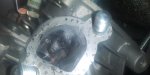
Here are some pics of the cylinder tube for the flowbench. There is also a gasket at the top that sticks up about 1/16th to 1/8th of an inch to be sure of an air tight seal with no leaks along the face of the head.
The head is on an adapter plate that 6"×6" and is lined up with a 70mm ID (the size of the cylinder bore) acrylic tube exactly where the cylinder would be that is 6" in length.
Yes. If I was concerned with how my head flows at a static rate compared to someone else's and/or wanted to put comparison numbers up for others to campare. As soon as I saw the numbers I thought they were high so I already knew that adjusting to 28" each time and posting exact 28" numbers was pointless so I just got close on a few and then wanted to see how much variance I had with the vac controller as well as get numbers at lower levels. While atmospheric pressure remains pretty constant the actual "suction" that the head goes through fluctuates greatly. After I calibrate my bench and get some more accurate numbers I will adjust to 28" at each lift and post them that way for comparison. I might do it for 10" also. But, to me, flow numbers at a single static depression is only a little bit useful. I will probably focus on numbers at higher valve events around 10"-18".
It's my opinion that the flowbench is much better suited for a data collection device rather than something that will give you hard answers on how a head will perform on a running engine. How many times will a trick head with big flowbench numbers gets out-performed by a modest head? More often than people like to admit! People want to believe that all of the time, effort and/or money was well spent and when it's not they might not admit it. Just throwing a head on a flowbench and getting a run of cfm numbers at 28" only tells you how much dry air can be pulled through at 28". It is better than nothing, for sure, but it's by far not a great indicator of actual real world performance.
After I calibrate my bench I plan on getting flow numbers at 10", 14", 18", 22", 25", 28", 30", 34", 40", 60" and dynamic with each valve lift and plot them on a chart. This way I can build a profile of the characteristics of the head and how it affects the behavior of the air flowing through it. Since there is a direct correlation between the amount of suction and cfm flow under ideal circumstances you can start to notice where a head might behave well at 10" but not gain the proper amount cfm increase at 28" as it should ideally, possibly pointing out a point that is causing too much turbulence. This way you can start to get an idea of the characteristics of what you are testing. That way when you make changes you can better understand whether or not the change was good or not and how much so. Between piston movement, fluctuating piston speeds, exhaust overlap, valve movements, sonic pressures, air/fuel speed fluctuations, etc the actual pressures are very dynamic even though the atmospheric pressure pushing in is consistent. The differences in pressures in the system can fluctuate how well and how much air can move through it at different times as well as how it behaves and alters the mixture. Sometimes you want the mixture to sheer to atomize fuel at different spots and sometimes you want it to flow smooth, sometimes it's best for it to flow smoother at higher pressure and sheer at lower pressure or vice-versa. Some times you want a good amount of swirl at certain air speeds but less swirl at higher speeds to avoid washout or fuel fling. You have to be able to get a sense of the behavior at different speeds and pressures in order to use it in a way that is actually beneficial as an aid to determine how well it will perform in real life. That way you can make changes and get an idea of how each change has affected the characteristics of the system in how it alters not only how much it can flow but if it presents any other characteristics at different speeds or pressures. Just taking a static test of 28" won't get you nearly as much information.
Since I am using very sensitive equipment for the readings over water in tubes that smootges out a lot of the fluctuations due to specific gravity, density and surface tension properties I can observe the real-time fluctuations to help get an idea if the system is more or less settled, turbulent, smooth, etc. for a better understanding of the characteristics of the system (head, port, valve seat area, exhaust, etc) that I am testing and watch it smooth out or become more more unstable with each little adjustment. I will make symbolic or numeric notes to keep track of these as well.
While it's good to have a comparative number that is representative of the average atmospheric pressure I think that if that's all you test at or look at when considering a part then you are missing out on a lot of important information that is much more detrimental to how a part would perform. If you put two heads on a flowbench that flowed exactly the same numbers throughout the valve lifts at 28" they can still perform much different in real life on the same engine. Now if you flowed them at 10" and 35" along with the 28" you would see differences in numbers at 10" and 35" even though they flowed identical at 28". Now if you use the flowbench as a data collection device and flow many at many different depression rates you can start to back engineer what a better performing head for a particular engine would present characteristically and make adjustments in those areas to make real world gains/efficiencies.
Thats my point. 28" is the standard for testing to achieve consistent flow numbers and to compare flow numbers. You are right 28" is 1 psi and every valve lift should be tested at 28". Every size orfice you flow will not be 28" of pressure but your machine should increase or decrease so you can take your CFM reading at 28".
Carbs are flow tested using 20.4" because the carb manufacturers are looking at the fuel/ air ratio the and engine needs. Not just air flow. Someone back in time (much smarter then me! LOL) decided that 20.4 was a corrected value to test and market carburetors at.
I would take the going by sound with a grain of salt. Years ago I was at the guy's shop that has the flow bench and another gentleman was there claiming the numbers mean nothing and the sound was more important. Well the flow bench owner quickly did a demo for us that proved that is not always the case. Made a believer out of me and the other guy. It still is of importance, but its not the only thing you should be going by. If it was why even have any gauges? LOL Back to the testing at 28". This is the way I was taught and seems to be when someone is stating flow number they are usually at 28" just the way I learned and the way I always did it.
Dyno are another can of worms! We have engine builders on both sides of the state here. The dyno numbers that come from the westside of the state are always higher then the eastside of the state! Yet the east motors will equal or out perform the west engines.Higher numbers sell and I will leave it at that.
As for the sound thing I think it is more about the guy working on the same head and port design for the same engine and the difference between the alterations made would be better detected by a well trained ear, especially since tge actual flow numbers when fine tunning don't actually move much. It's a fine tunning thing on heads for engines that you are very familiar with. So a builder will figure out what combo works for cars on each track and to the driver's drive style. He builds up his arsenal of engine combinations and knows where the numbers should get close to with his exact tweaks that he does. Then when the numbers get close you fine tune by ear to get the right balance, pitch, etc. So the numbers are used but the fine tuning of the characteristics that they are looking for is not a number, but a sense of feeling that you hone in on that has more to it than any simple number can present.
In my opinion you HAVE use something other than a device that spits out a hollow number if you are dealing with things that rely on more than just numbers. Since there is way more to a great performing head compared to a sluggish performing head than just the simple numbers you can test , then without including more ways of pulling data you are just guessing. Our ears and sense of touch are very sensitive and are good devices to use to help determine many different and subtle differences. With practice they can become more useful than the simple number generating devices. Most regular people without knowing much about a car can listen to 3 different engines and tell which ones make more power in classic musclecar type set-ups. I watched my dad build engines all my life. I have witnessed him diagnose an engine he had never seen before with only his ear and figure out exactly what was wrong that others could not figure out with diagnostic tools more times than I care to try to count. To this day Richard Petty can walk up to one of his Nascar Cup cars and tell if a cylinder is running too rich or lean and point to which cylinder it is. A well trained set of human sensory modules should never be left out of the equation doing most anything in life... especially when working on or building an engine.
For instance, when you check your oil. If you take the dipstick out and look at it you can see where the oil level is and the color. That gives you some indication of fluid level, whether it might be using oil and a slight indication of age by the color. You can now wipe some off in between your fingers and feel how slippery it is to give you a much more accurate idea on the age and viscosity due to how slippery it is. Then you can smell it. You can add another layer to the age as well as possible problems by whether there is coolent or fuel in the oil by the smell it has. It could smell burndt, life fuel, like coolant, etc. How many diagnostic devices would you need to gain as much information? How long would it take to get the devices hooked up? Our senses and our brains' ability to diagnose things are phenomenal and the more you know what to focus on and the more you use the skills the better they get. They should not be underestimated IMHO.
As far as engine dynos go there are so many variables thats its pretty silly to try to have exact comparisons. Just the altitude between the west and east sides of the state could be enough for a variation in numbers. A lot can be just the testing techniques. My dad would normally have lower numbers on his dyno than others. If he put an engine on from another shop where they said it pulled X amount he would assure the person beforehand that it would probably put out less on his but that didn't mean that they were lying... he just had a dyno that read more conservative.
This scenario happened a lot with my dad's customers: My dad would dyno tune an engine for someone and give them the numbers. They would go out and run it and be very happy. But then they would talk to someone who had an engine from another place that said they could get X amount out and they would go to them to have them work on it thinking they could go even faster only to end up being slower. After taking it back to the other shop and telling them that it was worse they eventually ended back at my dad's shop to get it back to where it was. A few of them took it to the other shop just to get a dyno number for comparison sake and it would be more than what my dad told them.
The process of taking a dynamic torque measurement can be difficult to get perfect, let alone factoring in test procedures and other variables. Then you have to know what compromises to make to target the specific performance that you want. Numbers can be helpful but there are more things that goes into a properly designed performance engine than just numbers.
Here are some pics of the cylinder tube for the flowbench. There is also a gasket at the top that sticks up about 1/16th to 1/8th of an inch to be sure of an air tight seal with no leaks along the face of the head.
Attachments
-
 20200805_083715.jpg3.1 MB · Views: 1
 -
 20200805_084059.jpg4.7 MB · Views: 1
Last edited:
I think your way over thinking flow testing, but has long has you achieve what your looking for all is good. It also seems I use flow testing slightly different (or for different reasons). My flow testing is mostly for comparing parts to see which ones flow better has most of the rules I deal with don't allow us to modify things. This is where accurate numbers and consistent test results are required. If a carb is sold has a 500 CFM I want to know exactly what it flows. Due to production there are always good, midrange, and poor quality casings. So we are always searching for the "cream of the crop". Somethings like valve seat angles, heights, and widths are some things we play with to increase flow, but there is only so much you can squeeze out with the tight rules we have to deal with.
Its also funny how so many people I've talked to have said once you start flow testing you will start looking for epoxy putty. Bigger isn't always better.
Its also funny how so many people I've talked to have said once you start flow testing you will start looking for epoxy putty. Bigger isn't always better.
TheInspiredFool
Member
- Messages
- 143
- Reaction score
- 10
I think your way over thinking flow testing, but has long has you achieve what your looking for all is good. It also seems I use flow testing slightly different (or for different reasons). My flow testing is mostly for comparing parts to see which ones flow better has most of the rules I deal with don't allow us to modify things. This is where accurate numbers and consistent test results are required. If a carb is sold has a 500 CFM I want to know exactly what it flows. Due to production there are always good, midrange, and poor quality casings. So we are always searching for the "cream of the crop". Somethings like valve seat angles, heights, and widths are some things we play with to increase flow, but there is only so much you can squeeze out with the tight rules we have to deal with.
Its also funny how so many people I've talked to have said once you start flow testing you will start looking for epoxy putty. Bigger isn't always better.
We definitely have different goals for flow testing. When focusing on intake and exhaust systems and trying to alter flow, velocity, swirl, equal valve pressure as well as introduce or eliminate sheer at various places I think you can get much more of an idea by varying test depression and graphing the results. If you just focus on what part flows the most I guess you wouldn't hve much of a need for a testing processes like mine. No matter what your testing more info can create a bigger overall picture that you can use to better determine characteristics of the part. You can have unnecessary data but never too much data. I am naturally very analytical and look for patterns to better understand and figure things out as much as possible. It's just applying more of a scientific method to better understand and figure out the characteristics instead of going off from just one test pressure. I feel it's a better process. I could be wrong and I don't presume others are wrong. I just do things my way in a way to gain a better understanding and build a database that could start to create a better level of understanding that I would otherwise not be able to have without more comprehensive testing.
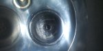
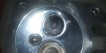
I totally agree with the epoxy thing. That's my reasoning for this build. This is the intake port below. I test for proper flow, port speed, balance, stability, swirl, valve seat curtain pressure, etc. It's difficult to get an understanding of any of those except max flow unless you put together different tests and build a database. If you just look at the numbers then you are missing out on all of the important things. As long as you have adequate flow numbers for your valve events, piston speed, displacement, etc then the max flow number is the least important part of the puzzle. So if you just continue to focus on max flow numbers at a given depression you are ignoring the characteristics that truely make the difference between great performance and poor performance.
I would suggest looking closer at the valve seat/valve curtain areas at low to mid lift with high depressions and tinker with trying to build a seat with good flow at low lift that will also induce a sheer to better atomize the fuel, build a valve bowl that helps to equalize the pressure around the valve, proper port speeds and induce swirl at low lift but a lighter swirl at mid and high lift. Many circle track guys spend tons of money on a few cfm more carbs and then have low port speeds, crappy atomization and don't take advantage of head scavenging, and then put too big of exhaust on. If your $1200 534cfm carb is running on an engine with a BSFC of 70% and another guy spends $500 on valve seat work for a proper balanced head that delivers a BSFC of 85% with a cheap carb that only flows 485cfm it will outperform the expensive carbed engine in every aspect. Efficiency is king. Learn where you need the power for the track you race at and learn what compromises you can make that takes the least away from what your goal is. Then make the system as efficient for your specific needs. Once it's optimized then you can gain more with higher dollar stuff but it won't make much of a difference if your system isn't efficient.
If you are just making money flowing parts then it's easy money and flowing at a single depression is all they are looking for. But if you are trying to help produce the most competitive engine then valve seats, port shape, port speed, exhaust tunning, etc is by far where you will make the biggest differences and best gains. Especially if you can alter the ports of a stock head with epoxy and porting, or just epoxy. If that's the case then you might want to try out my testing procedures then. If it was easy and straightforward than anyone with a flowbench would be able to build top competitive engines and there wouldn't be certain builders who consistently build much more competitive engines than other builders with the same flowbench and resources. Most of the classes only care about displacement, aftermarket internals and power adders. The open areas that can be altered are still very important like the valve seats. The biggest and most competitive builders spend many hours on the valve seat area and consider it one of the best places that you can improve performance. Efficiency of what air you can flow and quality of air/fuel mixture is more important than total air you can get. The efficiency improves your power throught the entire range whereas the restriction of the amount of air is only a constraint during the largest part of demand. If you can make the system more efficient than you start filling the cylinder sooner and packing it in harder so that you effectively reduce the total needed cfm needed because it's more efficient.
I guess I am more on the side of having more data and a mindset of trying to understand thatcharacteristics is better than just doing single depression testing much like the philosophy of overthinking something is usually much better than underthinking something. KISS (Keep It Simple Stupid) doesn't work so well when you are trying to harmonize a whole gamut of physics principles to be as efficient as possible in an environment as volatile as those associated with an Otto Cycle engine. Just saying.
A flowbench is only as useful as the power of depression it can produce and the accuracy that it can produce it at. The rest of the usefulness comes in how the operator chooses to use it.
__________________________________________________________________________________
On another note:
The guy that did the head work and machining for my dad's race engines would flow the whole system together from carb to exhaust manifold/header while it was on the engine. He would flow components separately but the final adjustments were a "whole system balanced flow" where he made sure things worked together the way he wanted them to. I always thought that would be the best way to get accurate information and have been trying to figure out the best process to incorporate it.I thought about running an electric motor to the shaft and turning the engine that way, gathering info from the spark plug area as well as the exhaust. Hmm.. Or just put vaccum to the exhaust with a metered spot ahead of the vacuum as well as in the sparkplug area and take data from both areas.
________________________________________________________________________
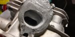
I had a little free time today so I did some port work on the exhaust. I pushed the valve bowl deeper, inverted the top and bottom of the bowl a bit a bit and raised and channeled the roof. I also managed to knick the valve seat face and took off some wall of the valve guide that I didn't mean to do. The valve seat is fine and I might grind the valve guide down a bit anyway. All-in-all I am satisfied with the shape and progress made today. I have a bit more to do and then I will prep the anchors and get ready for epoxy.
Attachments
-
 20200710_115005_HDR.jpg2.4 MB · Views: 2
 -
 20200819_004151.jpg2.3 MB · Views: 1
 -
 20200819_004138.jpg2.6 MB · Views: 2
 -
 20200819_004059.jpg2.8 MB · Views: 1
Last edited:
TheInspiredFool
Member
- Messages
- 143
- Reaction score
- 10
__________________________________________________________________
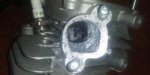
I worked on the exhaust port more, then prepped for epoxy, laid the epoxy, shaped it then did another light layer. I am going to shape it once more before putting it on the flow bench to blow flow through it.
With the exhaust I deepened the valve bowl and raised the two walls that act as the roof when the head is on the engine. Hot gases like to go "up". The rapid expansion of gases quickly search to escape to occupy a much less dense space so they can expand so I inverted the bowl slightly and pushed the bowl deeper to create a great place for them to escape and expand to from the combustion chamber. Once there the gases will be both pulled by the last pulses of exhaust cycles as well as traveling to the much lower atmospheric pressure at the end of the 2 or 3 stage exhaust header. I tightened the exhaust port by raising the short turn radius wall and corresponding wall up to provide an easier turn radius to prevent turbulence, as well as lead it to a size that should be sufficient enough cross-sectional area to allow plenty of flow at maximum demand but a small enough cross-sectional area that would be considered a tightened port (over stock) in order to increase the velocity/speed that the gases will move. This should increase the scavenging effect from as soon as the exhaust openes all the way until it closes over the stock port but also have a better laminar flowcompared to the much larger and sharper turn short turn radius of the stock port. I have also changed the exhaust port exit angle, position and shape to improve overall flow. The exhaust port should match nicely and be a nice compliment to the velocity of the intake port now.
The trick to maximize performance is to be able to flow the maximum needed volume of air at the highest demand in a system that can balance the compromise between maximum flow and proper velocity for your specific engine the best. For a massed produced industrial engine the compromise scenario is time vs money vs performance vs compliance. As long as the engine makes the stated HP and runs well enough to power some light industrial machine the performance side is not worried about... it is, afterall, just an industrial engine and not designed for performance or high rpm. In order to lower cost they must have the ability to produce the head as quickly as possible. The quickest way is to just drill a hole for the valve bowl and another for the port. They determine a shape and angle to improve flow and then again, as long as it runs ok the time spent on performance stops. These engines are made to basically run at a specific speed or against the governor which is set by federal laws at 3600rpm, run a piece of equipment enough to get the job done and do it while meeting the emissions standards, compact size for consumer convenience, and shipping costs, etc. They build them as cheap and as quickly as possible to meet that criteria and make as much profit as possible. They have to make compromises due to cost, build time, emissions, noise restrictions, engine compactness, etc. as well as they have built it for a different purpose than to go on a go kart. Once many of those restrictions and compromises are no longer needed the design can be altered to improve performance. It's my belief that the ports are one simple area you can adjust to improve performance.
So just because an engine is designed and built with large ports does not mean that they are optimized for performance. We are free from many of the compromises that the original engineers were constrained with. With much more time to spend creating proper shaped, angled and sized ports we can gain better performance. Once you are allowed to remove the restrictive intake and exhaust we can then provide proper intake and exhaust systems. Unfortunately, IMHO people often go too far to the other way, from restrictive to not enough restriction... which is better said as the engines go from having restrictions on the intake and exhaust to not properly controlling the pumping characteristics of the engine to optimize performance while in stock form. Once you alter the cam and stroke and other internals it alters how the engine pumps air and changes the demand drastically. But in stock configuration the air need with the piston speed, valve /cam events, timing, etc there is just not a need for large carbs, intake runners, ports, or big exhausts. Because of the mild cam, low overlap, slower piston speeds and timing it the engine struggles to move the larger volumes of air into and out of the engine quickly enough to run at a high BSFC or VE. The reson that a larger carb with more fuel improves the performance is because there is the amount of air allowed into the system is excessive. You need more fuel to balance the a/f ratio. When you put a larger intake runner and carb on you only get a marginal bump in performance. If tge system was better at controlling the flow and speed of the air then a bump in fuel introcuced to the charge would be almost an almost equal bump in BSFC, i.e. power produced.
So there is another rant as to the reason why I am altering the head this way and my personal thinking behind it. Once I calibrate tge flowbench and I see the numbers I want I will put the engine back together and see how it performs. That will be the true test to whether I went in the right direction or spent a lot of time screwing up a head. My free time is getting less and less so it's beginning to look like a race to completion before much I go back to not having much free time to monkey with this. I would like to be able to properly finish this up, grab anotger engine, build a dyno and do testing for comparison. We will see how that pans out.
Here are a few pics of the second application of epoxy. Now to finish adjusting the size, shape and smoothness and then on to the flowbench to get preliminary numbers.
I worked on the exhaust port more, then prepped for epoxy, laid the epoxy, shaped it then did another light layer. I am going to shape it once more before putting it on the flow bench to blow flow through it.
With the exhaust I deepened the valve bowl and raised the two walls that act as the roof when the head is on the engine. Hot gases like to go "up". The rapid expansion of gases quickly search to escape to occupy a much less dense space so they can expand so I inverted the bowl slightly and pushed the bowl deeper to create a great place for them to escape and expand to from the combustion chamber. Once there the gases will be both pulled by the last pulses of exhaust cycles as well as traveling to the much lower atmospheric pressure at the end of the 2 or 3 stage exhaust header. I tightened the exhaust port by raising the short turn radius wall and corresponding wall up to provide an easier turn radius to prevent turbulence, as well as lead it to a size that should be sufficient enough cross-sectional area to allow plenty of flow at maximum demand but a small enough cross-sectional area that would be considered a tightened port (over stock) in order to increase the velocity/speed that the gases will move. This should increase the scavenging effect from as soon as the exhaust openes all the way until it closes over the stock port but also have a better laminar flowcompared to the much larger and sharper turn short turn radius of the stock port. I have also changed the exhaust port exit angle, position and shape to improve overall flow. The exhaust port should match nicely and be a nice compliment to the velocity of the intake port now.
The trick to maximize performance is to be able to flow the maximum needed volume of air at the highest demand in a system that can balance the compromise between maximum flow and proper velocity for your specific engine the best. For a massed produced industrial engine the compromise scenario is time vs money vs performance vs compliance. As long as the engine makes the stated HP and runs well enough to power some light industrial machine the performance side is not worried about... it is, afterall, just an industrial engine and not designed for performance or high rpm. In order to lower cost they must have the ability to produce the head as quickly as possible. The quickest way is to just drill a hole for the valve bowl and another for the port. They determine a shape and angle to improve flow and then again, as long as it runs ok the time spent on performance stops. These engines are made to basically run at a specific speed or against the governor which is set by federal laws at 3600rpm, run a piece of equipment enough to get the job done and do it while meeting the emissions standards, compact size for consumer convenience, and shipping costs, etc. They build them as cheap and as quickly as possible to meet that criteria and make as much profit as possible. They have to make compromises due to cost, build time, emissions, noise restrictions, engine compactness, etc. as well as they have built it for a different purpose than to go on a go kart. Once many of those restrictions and compromises are no longer needed the design can be altered to improve performance. It's my belief that the ports are one simple area you can adjust to improve performance.
So just because an engine is designed and built with large ports does not mean that they are optimized for performance. We are free from many of the compromises that the original engineers were constrained with. With much more time to spend creating proper shaped, angled and sized ports we can gain better performance. Once you are allowed to remove the restrictive intake and exhaust we can then provide proper intake and exhaust systems. Unfortunately, IMHO people often go too far to the other way, from restrictive to not enough restriction... which is better said as the engines go from having restrictions on the intake and exhaust to not properly controlling the pumping characteristics of the engine to optimize performance while in stock form. Once you alter the cam and stroke and other internals it alters how the engine pumps air and changes the demand drastically. But in stock configuration the air need with the piston speed, valve /cam events, timing, etc there is just not a need for large carbs, intake runners, ports, or big exhausts. Because of the mild cam, low overlap, slower piston speeds and timing it the engine struggles to move the larger volumes of air into and out of the engine quickly enough to run at a high BSFC or VE. The reson that a larger carb with more fuel improves the performance is because there is the amount of air allowed into the system is excessive. You need more fuel to balance the a/f ratio. When you put a larger intake runner and carb on you only get a marginal bump in performance. If tge system was better at controlling the flow and speed of the air then a bump in fuel introcuced to the charge would be almost an almost equal bump in BSFC, i.e. power produced.
So there is another rant as to the reason why I am altering the head this way and my personal thinking behind it. Once I calibrate tge flowbench and I see the numbers I want I will put the engine back together and see how it performs. That will be the true test to whether I went in the right direction or spent a lot of time screwing up a head.
My free time is getting less and less so it's beginning to look like a race to completion before much I go back to not having much free time to monkey with this. I would like to be able to properly finish this up, grab anotger engine, build a dyno and do testing for comparison. We will see how that pans out.Here are a few pics of the second application of epoxy. Now to finish adjusting the size, shape and smoothness and then on to the flowbench to get preliminary numbers.
Attachments
-
 20200822_183826.jpg2.9 MB · Views: 2
 -
 20200822_183841.jpg2.6 MB · Views: 2
 -
 20200822_183850.jpg2.7 MB · Views: 2
I don't know what expoy your using but I've never found one or know of anyone that has had any luck with using it in the exhaust port and having it hold up. I tried it in a chainsaw exhaust port and it didn't last very long. I've talked to several other engine builders and no one claimed to have any luck in the exhaust port. Intake port, now thats a different story. I've found plain old JB weld (not the quick set) to work very good in intake ports and manifolds. The key to making it survive is in your prep work.
TheInspiredFool
Member
- Messages
- 143
- Reaction score
- 10
I don't know what expoy your using but I've never found one or know of anyone that has had any luck with using it in the exhaust port and having it hold up. I tried it in a chainsaw exhaust port and it didn't last very long. I've talked to several other engine builders and no one claimed to have any luck in the exhaust port. Intake port, now thats a different story. I've found plain old JB weld (not the quick set) to work very good in intake ports and manifolds. The key to making it survive is in your prep work.
Thanks vpd, I was worried about it. I spent a lot of careful time on prep work. I have an anchor, roughed the ports up well and created many recesses for the epoxy to fill in for further anchoring. I then cleaned the surface of any contaminants and/or oils just before applying the epoxy. I was thinking about trying to coat it with a high temp application that would help to insulate it from the direct heat and overlap the edges so that it didn't seperate at the edges. I thought about building up the port with cyanoacrylate with baking soda or just using the low temp aluminium welding rods. Leaving the exhaust port stock would have unbalanced the pumping efficiency. I don't think that I could keep enough heat in the head for the low-temp aluminum rods to create a good bond. I have been looking at ceramic hybrid coatings that might adhere well and control the heat to applied to the epoxy but it's hard to know what will adhere well to the epoxy, especially under such heat. I was thinking of coating it with JB Weld extreme heat.. I thought it would bond better with the other JB Weld origional than it would the aluminum. I was going to just try to paint on a high temp paint/coating (that withstands 2,000 degrees) with 3-5 layers but I am undecided. Anyone have any ideas?
The best way to prep aluminum in ports for epoxy that I've found is to rough the aluminum with a die grinder then immediately apply the epoxy. Seems like any type of cleaning just contaminants the aluminum and fresh ground is the cleanest. Like I said I've had no luck and have never heard of anyone that had any luck with epoxy in exhaust ports. You can try, all that will happen is it will loosen and be blown out the exhaust. I've even had JB weld fail in intake ports of chainsaws and it just burns it up and blows it out. No other damage to cylinder or piston.
If the exhaust port doesn't flow right try flowing it with your pipe/muffler on it and play with that and see if you can achieve what your looking for.
If the exhaust port doesn't flow right try flowing it with your pipe/muffler on it and play with that and see if you can achieve what your looking for.
TheInspiredFool
Member
- Messages
- 143
- Reaction score
- 10
Thanks again. I agree on the prep. I swabbed the port with 91% alcohol, then roughed it up with a twin cut carbide, grooved it with a flare head carbide, blew the chips out, screwed the anchor screw in and added epoxy. The anchor screw helps a lot as does the deep grooves with keeping the epoxy from moving and breaking loose from the port wall. I'm just worried about the epoxy melting away. I think a few coats of 2,000° treatment covering brushed on should help. I guess we will see.
Quote:
If the exhaust port doesn't flow right try flowing it with your pipe/muffler on it and play with that and see if you can achieve what your looking for.
Thanks for the advice. I was planning on flowing with the pipe on regardless, as well as the intake both alone and with the carb and then flow the whole system with my wet/full system plate that I made where I can adjust an 1/2" acrylic piece in a 70mm acrylic cylinder the full stoke that the piston can move. It helps that I am just flowing for a stock engine since it really doesn't need a ton of air, it just needs a balance of decent air and decent velocity. The big port allows for smaller but straighter ports which can still flow well but keep the velocity up. I might play with the diameters of the pipe as well as lengths for the different stages. Thanks again, though. I will keep that in mind and try flowing with the pipe on sooner than I would and see it it helps.
Oh, and thanks to you I am flowing different carbs, carb with air filter combos to get the best balance. I am trying to determine the depression that the carb sees andplaying around in that area to gain balance and get different carb flows. I doubt it will make much of a difference on this build but it's data for my notebook... and as you could probably guess, I love data! Lol So thanks for that, also.

Thanks again. I agree on the prep. I swabbed the port with 91% alcohol, then roughed it up with a twin cut carbide, grooved it with a flare head carbide, blew the chips out, screwed the anchor screw in and added epoxy. The anchor screw helps a lot as does the deep grooves with keeping the epoxy from moving and breaking loose from the port wall. I'm just worried about the epoxy melting away. I think a few coats of 2,000° treatment covering brushed on should help. I guess we will see.
Thanks for the advice. I was planning on flowing with the pipe on regardless, as well as the intake both alone and with the carb and then flow the whole system with my wet/full system plate that I made where I can adjust an 1/2" acrylic piece in a 70mm acrylic cylinder the full stoke that the piston can move. It helps that I am just flowing for a stock engine since it really doesn't need a ton of air, it just needs a balance of decent air and decent velocity. The big port allows for smaller but straighter ports which can still flow well but keep the velocity up. I might play with the diameters of the pipe as well as lengths for the different stages. Thanks again, though. I will keep that in mind and try flowing with the pipe on sooner than I would and see it it helps.
Oh, and thanks to you I am flowing different carbs, carb with air filter combos to get the best balance. I am trying to determine the depression that the carb sees andplaying around in that area to gain balance and get different carb flows. I doubt it will make much of a difference on this build but it's data for my notebook... and as you could probably guess, I love data! Lol So thanks for that, also.
Quote:
If the exhaust port doesn't flow right try flowing it with your pipe/muffler on it and play with that and see if you can achieve what your looking for.
Thanks for the advice. I was planning on flowing with the pipe on regardless, as well as the intake both alone and with the carb and then flow the whole system with my wet/full system plate that I made where I can adjust an 1/2" acrylic piece in a 70mm acrylic cylinder the full stoke that the piston can move. It helps that I am just flowing for a stock engine since it really doesn't need a ton of air, it just needs a balance of decent air and decent velocity. The big port allows for smaller but straighter ports which can still flow well but keep the velocity up. I might play with the diameters of the pipe as well as lengths for the different stages. Thanks again, though. I will keep that in mind and try flowing with the pipe on sooner than I would and see it it helps.
Oh, and thanks to you I am flowing different carbs, carb with air filter combos to get the best balance. I am trying to determine the depression that the carb sees andplaying around in that area to gain balance and get different carb flows. I doubt it will make much of a difference on this build but it's data for my notebook... and as you could probably guess, I love data! Lol So thanks for that, also.
The best way to prep aluminum in ports for epoxy that I've found is to rough the aluminum with a die grinder then immediately apply the epoxy. Seems like any type of cleaning just contaminants the aluminum and fresh ground is the cleanest. Like I said I've had no luck and have never heard of anyone that had any luck with epoxy in exhaust ports. You can try, all that will happen is it will loosen and be blown out the exhaust. I've even had JB weld fail in intake ports of chainsaws and it just burns it up and blows it out. No other damage to cylinder or piston.
If the exhaust port doesn't flow right try flowing it with your pipe/muffler on it and play with that and see if you can achieve what your looking for.
Thanks again. I agree on the prep. I swabbed the port with 91% alcohol, then roughed it up with a twin cut carbide, grooved it with a flare head carbide, blew the chips out, screwed the anchor screw in and added epoxy. The anchor screw helps a lot as does the deep grooves with keeping the epoxy from moving and breaking loose from the port wall. I'm just worried about the epoxy melting away. I think a few coats of 2,000° treatment covering brushed on should help. I guess we will see.
If the exhaust port doesn't flow right try flowing it with your pipe/muffler on it and play with that and see if you can achieve what your looking for.
Thanks for the advice. I was planning on flowing with the pipe on regardless, as well as the intake both alone and with the carb and then flow the whole system with my wet/full system plate that I made where I can adjust an 1/2" acrylic piece in a 70mm acrylic cylinder the full stoke that the piston can move. It helps that I am just flowing for a stock engine since it really doesn't need a ton of air, it just needs a balance of decent air and decent velocity. The big port allows for smaller but straighter ports which can still flow well but keep the velocity up. I might play with the diameters of the pipe as well as lengths for the different stages. Thanks again, though. I will keep that in mind and try flowing with the pipe on sooner than I would and see it it helps.
Oh, and thanks to you I am flowing different carbs, carb with air filter combos to get the best balance. I am trying to determine the depression that the carb sees andplaying around in that area to gain balance and get different carb flows. I doubt it will make much of a difference on this build but it's data for my notebook... and as you could probably guess, I love data! Lol So thanks for that, also.
TheInspiredFool
Member
- Messages
- 143
- Reaction score
- 10
I think I have the flowbench dialed in pretty close as far as accuracy goes in comparison with other flowbenches. I am running leakdown tests and test/calibration plate flows to see how the accuracy and repeatabilityis and make sure there are still no leaks since I have moved the bench around in my shop while doing other projects. Tests are within a few percent, repeatability is very good and tgere are no leaks. I think I will switch over to flowing the head again. I think the results will be much more accurate now. The initial tests were just too high for me to believe and I didn't even feel comfortable flowing for comparison between modifications. I knew I still needed to calibrate it but it was more off than I expected. Numbers to come soon if I can fit it in between the other projects I have going on.