2020 - Excalibur Electric Racing kart

Functional Artist

Well-known member
Messages
4,349
Reaction score
1,613
Location
Toledo, Ohio
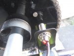
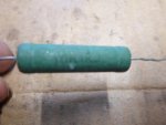
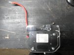
I added & am testing a DIY precharge circuit. :)
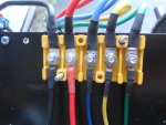
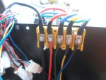
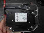
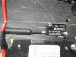
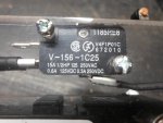
It's just a 10W 1KJ resistor & a momentary (micro) switch that is mounted across the contacts of the circuit breaker.

Here is a wiring diagram of it :sneaky:

* Notice how the switch is positioned/connected on the (VRC) or "restricted voltage" side of the resistor :2guns:

SAM_6833.JPG

I did a video to help explain & show how it works
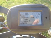
...& also, a quick demo of it "in action" :cool:


Attachments

  • SAM_6799.JPG
    SAM_6799.JPG
    319.9 KB · Views: 2
  • SAM_6836.JPG
    SAM_6836.JPG
    308.5 KB · Views: 2
  • SAM_6838.JPG
    SAM_6838.JPG
    307.8 KB · Views: 2
  • SAM_6840.JPG
    SAM_6840.JPG
    313.5 KB · Views: 2
  • SAM_6841.JPG
    SAM_6841.JPG
    306.2 KB · Views: 2

Functional Artist

Well-known member
Messages
4,349
Reaction score
1,613
Location
Toledo, Ohio
After getting most everything connected up, I precharged the system, engaged the circuit breaker & gave 'er a try
...but, the wheels went backwards :unsure:

So, I got out some of my old notes (for when I had ta switch the direction of rotation, on the 48V 1,800W Boma brushless motor)
...& did some re-arrangin' of the wires :sneaky:

Yup, that seems to work better :2guns:


Attachments

  • SAM_6647.JPG
    SAM_6647.JPG
    317.8 KB · Views: 3
  • SAM_6653.JPG
    SAM_6653.JPG
    304.8 KB · Views: 1
  • SAM_6661.JPG
    SAM_6661.JPG
    314.3 KB · Views: 3
  • SAM_6660.JPG
    SAM_6660.JPG
    315.2 KB · Views: 3

Functional Artist

Well-known member
Messages
4,349
Reaction score
1,613
Location
Toledo, Ohio
How to "do the math" to "size" a precharge resistor.

Let's use the 10W 1KJ resistor , that I installed on Excalibur, as an example :)

Current:
First, you have to figure out how much current will be flowing?
The basic equation is Volts = Amps x Resistance, V = I x R; In this case we know V and R, so we can calculate for current.
The basic equation is Current I = V/R= 60volts/1000 Ohms = 0.06 Amps. (the voltage divided by the resistance)
This will be the current flowing thru the resistor during inrush to fill the capacitors.

Power:
Next, is the resistor power rating adequately sized to handle this much current?
The basic equation is Power = I² x R , (the current squared, times the resistance)

Using the current as calculated above, and also, knowing the resistance, we come up with,
Power = (0.06 Amps) x (0.06 Amps) x 1000 Ohms = 3.6 Watts.

The numbers to precharge this 60V system would be
60V / 1,000 Ohms = 0.06A (current)
0.06A x 0.06A x 1,000 Ohms = 3.6W (power)

So, according to "the math", this 10W 1KJ resistor should be adequately sized to precharge this system. :cool:
 

Functional Artist

Well-known member
Messages
4,349
Reaction score
1,613
Location
Toledo, Ohio
Next, we need to know how long it takes to precharge the cap's in this system. :popcorn:
...so, we know how long to "hold the button" since this is a manual precharge circuit
...& to be sure that the required duration is not too long.

If it is for a short period, then it might be okay
...but, if it is a long time then the resistor will get hot.

How to calculate this?

Knowing R and C, we can calculate the Inrush time ~= 6 x R x C.
...the R is the resistance of the resistor (1,000 Ohm)
... the C is the total capacitance of the capacitators in the SC (940uF)
(which are in micro Farads, uF & requires you to divide by a million. 1uF = 0.000001 Farads)

*Remember, when we looked inside of the controller, there were 2 blue caps in parallel with an unpopulated spot for a 3rd. (2x 470uF = 940uF)

Here is what the math would look like:
T = 6 x R (1,000) x C (940) / 1,000,000
...& then doing the math, 6 x 1,000 x 940 / 1,000,000 = 5.64 seconds

So, now we know the precharge needs to be engaged at least 6 seconds, to adequately precharge this system
...& if only "used" for short periods like this it shouldn't get too hot either :)
 

Functional Artist

Well-known member
Messages
4,349
Reaction score
1,613
Location
Toledo, Ohio
Well, that's enough technical babble, for a minute :)
...anyone ready for some testin"?

First, let's get some RPM data on this 60V 2,000W brushless motor
...then, we'll get some MPH data

So, I got the RPM meter out & mounted the sensor on the frame, next to the sprocket
...then, stuck a magnet on the sprocket, to "signal" the sensor

Then, I precharged the circuit
...switched the breaker "on"
...switched the system "on"
...switched the RPM meter "on"
...switched the (3) speed switch into "low"
...activated the throttle pedal
...& let 'er "rip" :cool:

SAM_6953.JPG

Yup, I did a video to record the data :sifone:

* Donuts are @ the end :devil2:


Attachments

  • SAM_6954.JPG
    SAM_6954.JPG
    306 KB · Views: 3

Functional Artist

Well-known member
Messages
4,349
Reaction score
1,613
Location
Toledo, Ohio
After reviewing the RPM data for this 60V 2,000W brushless motor
...powered by (5) 12V 15AH SLA's (~64V top charge)
...& running @ a 6:1 GR (10T motor & 60T sprocket)
I wanted to record the data that I came up with :cool:

* I took the readings off of the sprocket (axle)
...so, we have to multiply those RPM reading, by the gear ratio, to calculate the motor's speed (RPM's)

Unloaded: (axle) (motor)
Low: 580 3,480
Med: 762 4,572
High: 942 5,652

Loaded:
Low: 500 3,000
Med: 675 4,050
High: 830 4,980

(max or peak)
Loaded:
Low: 520 3,120
Med: 695 4,170
High: 861 5,166

The "unloaded" numbers were pretty consistent
...but, the "loaded" numbers fluxuated, a lot due to varying road conditions
...so, watching the video, I also, looked for & recorded the top (max) RPM reading for each speed :thumbsup:
 

Functional Artist

Well-known member
Messages
4,349
Reaction score
1,613
Location
Toledo, Ohio
I finally got around to doin' some speed testing data while running @ 60V :)

Specs:
60VDC Battery pack (5- 12V 12AH SLA batteries with a top voltage level of ~64V) ;)
60V 3,000W Brushless motor
Gear Ratio is 6:1(10T drive sprocket & 60T driven sprocket)
Wheels are ~11" tall with a ~34" circumference (10.5x4.50-6 Unilli racing slicks)

So, it looks like this little kart does ~15MPH when in low speed
...~20MPH when @ med speed
...& she tops out @ ~25MPH :cool:

Here is my data collection video :sifone:

SAM_7082.JPG
 

Attachments

  • SAM_7083.JPG
    SAM_7083.JPG
    315.9 KB · Views: 5
  • SAM_7084.JPG
    SAM_7084.JPG
    318.3 KB · Views: 5
  • SAM_7085.JPG
    SAM_7085.JPG
    313.1 KB · Views: 4

Functional Artist

Well-known member
Messages
4,349
Reaction score
1,613
Location
Toledo, Ohio
Hi @Functional Artist
How does the performance compare to some of your other electric builds ?
Excalibur has the best performance, overall, of anything that I've built so far. ;)

The acceleration is awesome :cool:
...but, I must say, the top speed of "only" ~25MPH is very misleading, cause this thing really "flies" :auto:

The "Glexis" seems to be dialed in pretty good, cause the maneuverability is "superb".
* This is the first/only kart that, I've built or ridden, that can confidently take a turn "at full speed" :cheers2:

It seems that with this kart being so little/light & with the Akerman, Caster & Camber settings plus, with the weight of the driver & battery pack(s) nicely centered that when you turn the wheel, the COG shifts just "a bit"& she just "digs in" & turns without any noticeable understeer or oversteer, at all :banana:

*But, it's kinda hard on them front tires :eek:

The brakes work very well, for being just a band brake
...& they stop this kart quickly & firmly

So, in my opinion, the power to weight ratio (acceleration)
...& the power to brake ratio (braking) both seem good :sifone:SAM_7093.JPG
 

KMEFA

Active member
Messages
215
Reaction score
74
''Very nice'' !!

1' taller rear tires,, you should be able to hit 30+ without breaking a sweat. ;)

I
 

KMEFA

Active member
Messages
215
Reaction score
74
Added,,

What do you figure the weight of those 5 lead acid batts. at ?
I 'am guessing around 40lbs. ??


My wife's 36v BLDC Mini bike, it has a Sine wave 36 - 48v 1000w 12 fet ''self learning'' controller.
That one has 2 small leads on it, that you touch together with it powered up,, - ''if it runs backwards''.. Then you switch it off & then power it up again, & connect the leads for a moment,, to get the proper direction.
Don't have to mess with the phase & Hall wires.

My Buddies 48v 1800w, on his Minibike,, I had to switch the yellow & blue phase wires, & a green & yellow wire,, in one end of one of the Hall connectors, to get proper direction,, but that motor mounting is opposite of yours.
 
Last edited:

Functional Artist

Well-known member
Messages
4,349
Reaction score
1,613
Location
Toledo, Ohio

Functional Artist

Well-known member
Messages
4,349
Reaction score
1,613
Location
Toledo, Ohio
Added,,

What do you figure the weight of those 5 lead acid batts. at ?
I 'am guessing around 40lbs. ??


My wife's 36v BLDC Mini bike, it has a Sine wave 36 - 48v 1000w 12 fet ''self learning'' controller.
That one has 2 small leads on it, that you touch together with it powered up,, - ''if it runs backwards''.. Then you switch it off & then power it up again, & connect the leads for a moment,, to get the proper direction.
Don't have to mess with the phase & Hall wires.

My Buddies 48v 1800w, on his Minibike,, I had to switch the yellow & blue phase wires, & a green & yellow wire,, in one end of one of the Hall connectors, to get proper direction,, but that motor mounting is opposite of yours.
Have you checked out my Aerial Atom kart?

She's powered by a 60V 2,000W BLDC motor, (5) 12V 15AH SLA's with ~13" rear tires
& does ~35 MPH

(2) Building a go kart size Aerial Atom | DIY Go Karts

(308) Building a go kart sized Ariel Atom (slide show) - YouTube

(308) Ariel Atom Go Kart First Systems Check - YouTube
 

KMEFA

Active member
Messages
215
Reaction score
74
Am picking up a ''complete'' vintage later 80's Coyote ''Bullet'' sprint Kart chassis, Sun. Morn.
It's going to be powered by a 48v ''1109'' 2000w BLDC, ect.
Plan ''so far is'',, 2 - 48v 13s4p - BMS ''12ah'' packs in parallel.
All up chassis weight of that Kart is only supposed to be around 90lbs.
Figure both packs together @ around 10lbs.
Gearing I have calculated ''so far'' is :,, 6.9 - 1,, ''10 - 69''.
Also plan on 14+'' tires on back, w/ 6'' rims.

Built my Buddy a stripped down 48v 1800w Mini bike, with a 48v 1800w set up,, running 2 - 13s 3p - BMS packs in parallel.
Gearing on that is 6.1 - 1,, ''10 - 61''.
That thing ''flies'', even with my 210 lbs on it, & doesn't load down at all.
Tires on that are 14.3's.
AUW of that bike is 75lbs.

Am going to put a 1 1/4 -1/4 wall aluminum axel on my kart.
That axel only weighs 3 lbs., & will be just fine.
That's over 5lbs. less weight than the steel ones I was quoted.;)

It is pretty much just going to be a ''large subdivision '' street cruiser.:cool:
Will be building my buddy one also. (y)
He weighs around 25lbs. less than me, & will probably initially try out a 6.7 - 1 set up on his.

Am sure we will keep in touch. ✌️

Ian
 
Last edited:
Messages
73
Reaction score
5
Location
Albany, OR
I wanted to make some sort of automated precharge circuit for my project, and what ended up doing was using an Arduino-style MCU that just waits 5 seconds and activates a DPST relay to switch from the resistors to the direct power. I was using the MCU for other aspects of the go kart anyway, but this turned out to be very effective.
 

66dellwood

New member
Messages
14
Reaction score
9
What an awesome thread and project. Quick question on wiring the mechanical brake into the speed controller. If you already showed this, apologies for having missed it.

Is there a technique and/or products to neatly connect the "brake" connector on the controller to the brake pedal so the motor cuts out when the brake is applied? This is integrated nicely with electric scooter hand brake levers and was hoping for something similar with floor foot brake pedals for karts.

Asking b/c with a build for the grandson, he can't always apply enough pressure on the brake band drum to get quick stop. I would love to get regen braking-- just like Popi's Tesla.

thanks much.
great feedback and suggestions over here:
 

Utsavvp

New member
Messages
7
Reaction score
1
Next we needs to angle up the front of the frame, just a bit, on each side
…& then, we can weld the outer rails, to the inner rails :thumbsup:
(used a board to help keep 'em aligned)

Also, attached the spindle brackets
...angled 'em back just a bit
…& inward just a bit too :2guns:
(used another board to help keep 'em aligned in this direction too) :cheers2:

* All (4) wheels will be the same size (10.5" x 6" Unelli's)
...so, the spindle height has been adjusted accordingly, to align with the rear axle height
I could not understand why did you have to put the front wheel at an angular position and also inward. Sorry to annoy but a newbie here.
 
Top