2017 - El Moto

Functional Artist

Well-known member
Messages
4,371
Reaction score
1,636
Location
Toledo, Ohio
Finished the book
...took the test :thumbsup:

I was kinda nervous :ack2:

I know how to ride a motorcycle
...but, I haven't taken a test @ the BMV in like 35 years :smiley_omg:

Boom!
I "officially" have a "temporary" motorcycle driving/riding permit :wai:

I was so happy :bannana: :sifone:

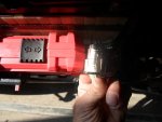
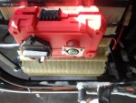
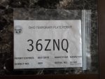
I went ahead & got license plates for the bike too :2guns:

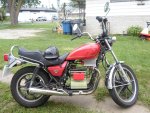
Since it's a 1980 Kawasaki (basically an antique) I was able to get "Historical" plates
(good forever, you don't have to renew yearly)
...but, the BMV lady was real adamant that these plates are only for going/driving/riding to shows

I was like, "Don't worry, I'll be "showing" it a lot :cornut:

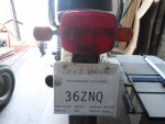
They gave me a piece of paper to use as a license plate until I get the real one
...they mail the "actual" plates (I guess they don't have "historical" motorcycle plates in stock)

So, I stuck it in a zip-lock bag & taped it right to
…"my own little sign" TEST VEHICLE STAY BACK :lolgoku:
 

Attachments

  • SAM_1576.jpg
    SAM_1576.jpg
    217.5 KB · Views: 0
  • SAM_1578.jpg
    SAM_1578.jpg
    232.7 KB · Views: 1

Functional Artist

Well-known member
Messages
4,371
Reaction score
1,636
Location
Toledo, Ohio
Ohio State law requires temporary (motorcycle) permit holders to

1.) Wear a DOT approved Helmet (first year minimum)
2.) No riding after dark
3.) No riding on the highway/interstate

I am kool with all of that :thumbsup:

I mainly want to test the "set up" & electrical components (amp draw, top speed, range etc.)

I needed a helmet :idea2:

So, I put an ad on the local Craigslist

New Rider Looking for a nice Motorcycle Helmet

I just got my temp permit & am looking for a free or low cost motorcycle helmet


Within (2) days I had several responses
...most were, I have an ad posted "check it out" (mostly ~$50.00+)
…& some were kinda far away (~20 miles)

Then, this guy replied that he had several to choose from ($20.00 - $30.00 ea.)
…& right here in town, even :thumbsup:

So, I went & checked 'em out

Yup, I brought me home a nice one ($20.00)
...with (2) tone black flames :2guns:
 

Attachments

  • SAM_1751.jpg
    SAM_1751.jpg
    506.1 KB · Views: 2
  • SAM_1754.jpg
    SAM_1754.jpg
    239.2 KB · Views: 0
  • SAM_1760.jpg
    SAM_1760.jpg
    205.3 KB · Views: 0

Functional Artist

Well-known member
Messages
4,371
Reaction score
1,636
Location
Toledo, Ohio
I still haven't heard back from that eBay seller yet :furious2:

So, while waiting, I went ahead & assembled a "mini meter"
...still need to monitor the balance of my "new" battery

I just put (2) of the digital voltage meters in a small plastic box
...with a (DPST) switch (wired differently, this time)

It's a Digital Battery Pack Balance Monitor :thumbsup:

https://www.youtube.com/watch?v=uzwUiSl0Azg
 

Attachments

  • SAM_1702.jpg
    SAM_1702.jpg
    251.2 KB · Views: 0
  • SAM_1693.jpg
    SAM_1693.jpg
    299.4 KB · Views: 0
  • SAM_1691.jpg
    SAM_1691.jpg
    301.8 KB · Views: 0
  • SAM_1688.jpg
    SAM_1688.jpg
    344.4 KB · Views: 0
  • SAM_1684.jpg
    SAM_1684.jpg
    307.8 KB · Views: 0
  • SAM_1721.jpg
    SAM_1721.jpg
    236.4 KB · Views: 0
  • SAM_1715.jpg
    SAM_1715.jpg
    354.4 KB · Views: 0
  • SAM_1713.jpg
    SAM_1713.jpg
    287.7 KB · Views: 0
  • SAM_1711.jpg
    SAM_1711.jpg
    269.2 KB · Views: 0
  • SAM_1709.jpg
    SAM_1709.jpg
    229.9 KB · Views: 0

Functional Artist

Well-known member
Messages
4,371
Reaction score
1,636
Location
Toledo, Ohio
Success!!!!

Yup, :iagree:

She "pulls" very smooth :thumbsup:

There were a few things I was concerned about :huh:

Would she "actually" be a little slower?

The (4) 12V 35AH SLA's, when fully charged, were ~53.2V
...the Volt battery, when fully charged, is only ~49V

So, far I haven't noticed a difference :wai:

I still have not "actually" tested the "top speed" or range/distance yet
...just playin' around & gettin' the "feel" of her :cheers2:

Here is another video that my daughter Desteny helped me make.

This way I could show how she rolls out from another perspective :2guns:

https://www.youtube.com/watch?v=aNEltShaPIE
 

Attachments

  • SAM_1770.jpg
    SAM_1770.jpg
    545.8 KB · Views: 0
  • SAM_1784.jpg
    SAM_1784.jpg
    428.2 KB · Views: 5

Functional Artist

Well-known member
Messages
4,371
Reaction score
1,636
Location
Toledo, Ohio
Nice job! But I would not feel safe on a silent "motor"cycle.

Thanks! :thumbsup:

This is "the way of the future" :2guns:
...any suggestions?

She's from 1980 maybe...Disco :smiley_omg: :roflol:

I got a couple of deer whistles :cheers2:
...but, their not gonna help warn pedestrians :huh:
...or on coming traffic :furious2:
 

Attachments

  • SAM_1861.jpg
    SAM_1861.jpg
    259.4 KB · Views: 0
  • SAM_1860.jpg
    SAM_1860.jpg
    244.9 KB · Views: 0
  • SAM_1856.jpg
    SAM_1856.jpg
    327.8 KB · Views: 0
  • SAM_1858.jpg
    SAM_1858.jpg
    195.8 KB · Views: 0
  • SAM_1857.jpg
    SAM_1857.jpg
    319 KB · Views: 0

Functional Artist

Well-known member
Messages
4,371
Reaction score
1,636
Location
Toledo, Ohio
Finally got the Yewi UY-600 battery chargers, that I ordered

They are "actually" really nice :thumbsup:

But, they didn't come with the "matching" XLR female charge receptacles

No big deal, they use these XLR plugs in the "making music" industry
...I picked up a couple ($5.00 ea.) from a local music/instrument store

Plugged a charger into one of the charge ports & checked the polarity with a multi-meter
...to figure out which pin is the positive (+) one & which pin is the negative (-) one

*Hmmmm, why does the meter read 47.6V?
 

Attachments

  • SAM_1816.jpg
    SAM_1816.jpg
    271.2 KB · Views: 1
  • SAM_1817.jpg
    SAM_1817.jpg
    210.9 KB · Views: 0
  • SAM_1819.jpg
    SAM_1819.jpg
    210.6 KB · Views: 0
  • SAM_1828.jpg
    SAM_1828.jpg
    215.8 KB · Views: 0
  • SAM_1827.jpg
    SAM_1827.jpg
    204.7 KB · Views: 0
  • SAM_1826.jpg
    SAM_1826.jpg
    198 KB · Views: 0
  • SAM_1823.jpg
    SAM_1823.jpg
    195.3 KB · Views: 0
  • SAM_1822.jpg
    SAM_1822.jpg
    212.9 KB · Views: 0

Functional Artist

Well-known member
Messages
4,371
Reaction score
1,636
Location
Toledo, Ohio
Once we know the polarity of the charger plug
...which is positive (+) pin & which is the negative (-) pin
(I marked the polarity right on the charger plug & the charge port, just to be sure) :idea2:

Now, we can solder the connector wires to the proper terminals on the charge port

I also double checked that the charge port would fit in the box
...it isn't too long & has clearance for the wires etc.

I looks like it will fit
...but, to be sure, I'll solder the connector wires on at a 90* angle :2guns:
 

Attachments

  • SAM_1838.jpg
    SAM_1838.jpg
    220 KB · Views: 0
  • SAM_1836.jpg
    SAM_1836.jpg
    198.9 KB · Views: 0
  • SAM_1854.jpg
    SAM_1854.jpg
    236 KB · Views: 2
  • SAM_1855.jpg
    SAM_1855.jpg
    255.6 KB · Views: 2

Functional Artist

Well-known member
Messages
4,371
Reaction score
1,636
Location
Toledo, Ohio
To mount the charge port into the box

First, we gotta drill a hole right in the center of the area that we have to work with
...right next to the circuit breaker (saved this area just for a charge port)

Then, use a step-drill bit to make the hole bigger
…& a bit bigger
…& then, just a little bit bigger than that

Almost :thumbsup:

Now, we gotta use the bigger bit :smiley_omg:

Yup, that'll do it :2guns:
 

Attachments

  • SAM_1846.jpg
    SAM_1846.jpg
    234.2 KB · Views: 0
  • SAM_1845.jpg
    SAM_1845.jpg
    232.7 KB · Views: 0
  • SAM_1844.jpg
    SAM_1844.jpg
    242.8 KB · Views: 0
  • SAM_1843.jpg
    SAM_1843.jpg
    268.5 KB · Views: 0
  • SAM_1842.jpg
    SAM_1842.jpg
    243.7 KB · Views: 0
  • SAM_1848.jpg
    SAM_1848.jpg
    188.5 KB · Views: 0
  • SAM_1847.jpg
    SAM_1847.jpg
    273.6 KB · Views: 0
  • SAM_1849.jpg
    SAM_1849.jpg
    199.4 KB · Views: 0

Functional Artist

Well-known member
Messages
4,371
Reaction score
1,636
Location
Toledo, Ohio
A couple of little chrome screws secures it down nice :thumbsup:

Now, to get 'er connected

By installing the charge port, in the box, next to the circuit breaker it only needs
...~6" of wire to connect the (red) positive (+) wire to the "Battery" side of the circuit breaker
…~ 10" of wire to connect the (black) negative (-) wire to the negative terminal of the battery pack
…& a couple of 1/4" ring terminals :2guns:

Double checked, for proper connection
...just to be sure
...before connecting my "new" charger

Yup, the charge port
...shows the same reading, as the battery pack it self :wai:

Connected the charger
...everything looks good :cheers2:
 

Attachments

  • SAM_1874.jpg
    SAM_1874.jpg
    208.4 KB · Views: 0
  • SAM_1872.jpg
    SAM_1872.jpg
    253.8 KB · Views: 0
  • SAM_1870.jpg
    SAM_1870.jpg
    244.7 KB · Views: 0
  • SAM_1868.jpg
    SAM_1868.jpg
    269.9 KB · Views: 0
  • SAM_1867.jpg
    SAM_1867.jpg
    243.1 KB · Views: 0

Functional Artist

Well-known member
Messages
4,371
Reaction score
1,636
Location
Toledo, Ohio
Well, I kinda "jumped the gun" when I "test" rode the bike last week :rolleyes:
...before even having the battery charger, to charge the battery back up

It shouldn't be a big deal, while doing research, I read that it's not as important to "immediately" recharge lithium batteries, like it is for the lead acid batteries
...& I only discharged it down to ~43V (no where near the ~38V "safe low limit"
...but, we still need to get 'er charged back up, for further testing :thumbsup:

No matter, we now have a "shinny new charger" :wai:

So, I attached our new charger to the bike (charge port)
...plugged it in
...turned it on
…& nothing

It turned on
...the fan began to spin (but, then stopped)
...the red LED light came on (indicating power/charger on)
…& the second LED came on but, it lit up green (indicating full charge)

It should be red, indicating the charger is charging the battery pack back up
...then turn green, to indicate "when" the battery pack is fully charged


That can't be :ack2:
...my Amp/Volt meter, on the Tri-Quad, reads ~43V
...the balance monitors each read 21.5V
…I even double checked with the multi-meter (right @ the battery terminals) & it still shows ~43V

Really? :censored: :censored:

Uggg :mad: :smiley_omg:

Why, why, why is my new battery charger not working? :mad2: :furious2:
 

Attachments

  • SAM_1873.jpg
    SAM_1873.jpg
    236 KB · Views: 0
  • SAM_1874.jpg
    SAM_1874.jpg
    208.4 KB · Views: 0

Functional Artist

Well-known member
Messages
4,371
Reaction score
1,636
Location
Toledo, Ohio
So, I sent them a message

Hello,
I discharged one of my 45V battery packs down to ~43V. (It started off at ~49V)
I connected the charger to it but, it did not charge the battery back up to ~49V, like it was supposed to.
After connecting the charger (1) red light came on & (1) green light came on.
(the fan came on for a couple of seconds, then turned off)
According to the manual, while charging, both red lights should be on.
When charging is complete (1) red light & (1) green light should be on.
I checked to be sure everything is connected properly & I double checked that the (2) fuses were in good working order.
I do not understand why but, it is not charging the battery pack back up to the 49V preset top charge, like I requested.
I sent a picture of me checking the polarity & output of one of the new chargers.
(I have the chargers XLR plug, connected to a female XLR charge port, with a meter attached)
I was also surprised that they didn't come with matching female receptacles.
(for connecting it to the battery/vehicle) I assumed that they did.
Please help.
Thank you, Kevin


While waiting & trying to figure this thing out, I noticed that the AC input 200-240V was marked
...in the manual & on the charger it self.

Hmmm, it should be 110V

So, I sent them another message (with a picture) about the 200-240V being marked on the charger
...but, it having a 110V AC input plug.

This was their response:


Dear Kevin,
Sorry for the troubles, the chargers are 220v ac input, we made a mistake on input voltage, and caused the problem.
Do you have electronics engineers which can solder the PCB? It is very easy to change the 220vac to 110vac, just solder a jump wire.
I am very sorry for the mistake, we would like to replace but the freight is too high, can you do the changes? We can provide a discount for next order as compensation.
Best regards,


So, I sent them another message,

I don't feel comfortable with "fixing" my new charger.
What if I don't do it right? & even if I am successful, I am still relying on a brand new "fixed" battery charger.
Not to be rude but, can you please send me the "right" battery charger, the one I "actually" special ordered?

Yewi UY600
10A lithium battery charger
Top charge preset to 49V
AC input plug- #9 (3-prong USA)
Dc output plug- #E (3-pin XLR)


Their response:

Hi Kevin,
Sorry for the troubles, we would like to ask you to send the chargers to our business partner in USA, they will help to change the chargers, i will send you the address later.

Best regards,

Later!? WTF

OOOOH, I hate :censored: :censored: :censored: Chinese :censored::censored::censored: companies
 

Attachments

  • SAM_1816.jpg
    SAM_1816.jpg
    271.2 KB · Views: 2
  • SAM_1892.jpg
    SAM_1892.jpg
    306.8 KB · Views: 1
  • HTB1EuaTKeuSBuNjSszi762q8pXaD.jpg
    HTB1EuaTKeuSBuNjSszi762q8pXaD.jpg
    43.6 KB · Views: 0

Functional Artist

Well-known member
Messages
4,371
Reaction score
1,636
Location
Toledo, Ohio
Here is another message from Yewi

"The instruction is attached, use 17awb wires to connect the two places, for the NTC points, the green NTC can be removed out."


So, it looks like I need to add a jumper wire connecting A & B
...but, do I simply remove the green NTC? (just clip it out?) :huh:

or :idea2:

Am I supposed to remove the green NTC & add a second jumper wire?

Wow!, what happened to "just solder a jump wire"? :smiley_omg:
 

Attachments

  • Yewi UY600 110V repair.jpg
    Yewi UY600 110V repair.jpg
    254.9 KB · Views: 2
  • HTB1EuaTKeuSBuNjSszi762q8pXaD.jpg
    HTB1EuaTKeuSBuNjSszi762q8pXaD.jpg
    43.6 KB · Views: 1

Functional Artist

Well-known member
Messages
4,371
Reaction score
1,636
Location
Toledo, Ohio
Stand back :smiley_omg:

I'm goin' in :thumbsup:
(hope I don't mess this up)

First, I removed (8) small Phillips head screws
…(4) on each end

Then, gently pulled the end covers loose (to see what we had to work with)

I assumed (wrong) that the circuit board would just slide right out

Nope, looking inside with a light, I see that there are things that are soldered to the circuit board
...& also "glued" to the inside of the aluminum box

Hmmm :idea2:

Well, it looks like the "green thing" is right here at the edge of the circuit board
…& the (2) "jumper spots" (A) & (B) seem to be kinda accessible too

I think we can do it! :wai:
 

Attachments

  • SAM_1933.jpg
    SAM_1933.jpg
    253.5 KB · Views: 0
  • SAM_1934.jpg
    SAM_1934.jpg
    210.4 KB · Views: 0
  • SAM_1935.jpg
    SAM_1935.jpg
    224.9 KB · Views: 0
  • SAM_1938.jpg
    SAM_1938.jpg
    205.9 KB · Views: 0
  • SAM_1943.jpg
    SAM_1943.jpg
    221.9 KB · Views: 0
  • SAM_1945.jpg
    SAM_1945.jpg
    240.9 KB · Views: 0

Functional Artist

Well-known member
Messages
4,371
Reaction score
1,636
Location
Toledo, Ohio
Step 1.)
I "sniped" the Lima bean out :thumbsup:

OK, now we need (2) jumper wires
...the "factory" recommended (oddball) 17 AWG
(the next size bigger is usually better)

Step 2.)
So, I cut (2) ~ 1" pieces of orange 16 g. wire

Step 3.)
I tinned both of the ends of both jumper wires

Step 4.)
I used the soldering iron to melt a small blob of solder (to tin) each of the first "jumper wire" attachment spots (A) & (B)

Step 5.)
I held (1) end of a jumper wire to (1) of the solder blobs (B)
…& used the soldering iron to solder them together

Step 6.)
Then, I held the other end to the second solder blob (A)
…& soldered them together too

Lookin' good so far :2guns:
 

Attachments

  • SAM_1956.jpg
    SAM_1956.jpg
    189.4 KB · Views: 0
  • SAM_1954.jpg
    SAM_1954.jpg
    226.3 KB · Views: 0
  • SAM_1953.jpg
    SAM_1953.jpg
    213.7 KB · Views: 0
  • SAM_1949.jpg
    SAM_1949.jpg
    251.1 KB · Views: 0
  • SAM_1947.jpg
    SAM_1947.jpg
    230.8 KB · Views: 0
  • SAM_1959.jpg
    SAM_1959.jpg
    196.4 KB · Views: 0
  • SAM_1963.jpg
    SAM_1963.jpg
    233.7 KB · Views: 1
  • HTB1EuaTKeuSBuNjSszi762q8pXaD.jpg
    HTB1EuaTKeuSBuNjSszi762q8pXaD.jpg
    43.6 KB · Views: 0
  • SAM_1966.jpg
    SAM_1966.jpg
    235.4 KB · Views: 1
  • SAM_1970.jpg
    SAM_1970.jpg
    236.1 KB · Views: 2
Top