2017 - El Moto

Functional Artist

Well-known member
Messages
5,275
Reaction score
2,713
Location
Toledo, Ohio
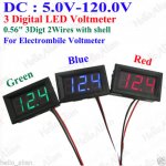
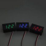
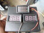
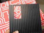
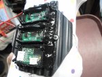
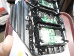
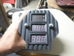
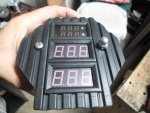
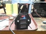
Might be an option to get the square boxes, and place their innards into the roundy gauge. Should save a 1/2" for gauge

Thanks, I was kinda thinkin' the same thing

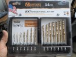
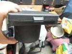
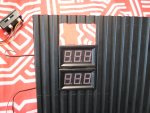
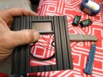
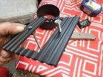
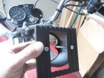
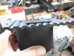
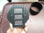
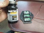
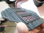
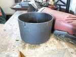
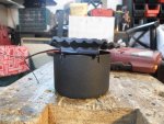
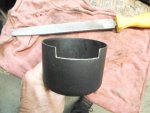
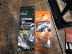
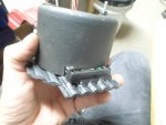
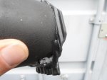
I came across this drill bit box (I got this thing for drill bit boxes lately)
...it was ~4" x ~5" x ~1" deep

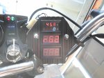
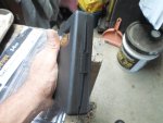
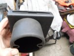
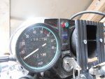
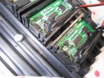
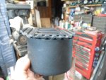
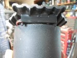
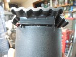
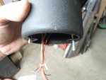
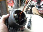
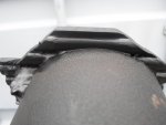
It woulda looked kool, held the gauges nicely, provided easy access for wiring & I coulda attached to the top of the black gauge cup
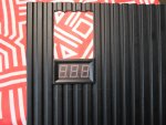
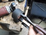
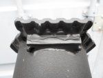
...but it was too big :ack2:

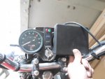
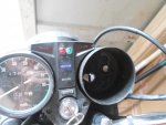
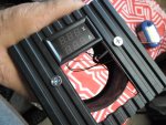
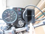
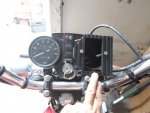
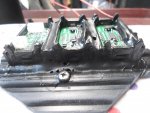
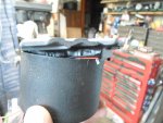
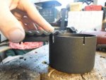
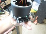
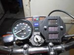
The upper corner would cover the right turn signal indicator
…& the lower corner would of been in the way/blocking the key switch

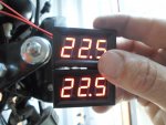
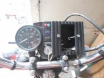
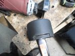
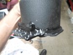
If I move it over enough to clear the indicator & key switch
...it's hanging half way off of the cup

Nope, not gonna work

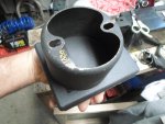
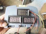
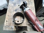
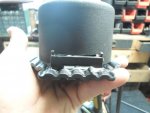
Gonna have to get creative
...goin' "Custom" :2guns:

BRB
 

Attachments

  • SAM_1258.jpg
    SAM_1258.jpg
    298 KB · Views: 0
  • SAM_1263.jpg
    SAM_1263.jpg
    237.5 KB · Views: 0
  • SAM_1265.jpg
    SAM_1265.jpg
    266.1 KB · Views: 0
  • SAM_1266.jpg
    SAM_1266.jpg
    245.9 KB · Views: 0
  • SAM_1268.jpg
    SAM_1268.jpg
    204 KB · Views: 0
  • SAM_1282.jpg
    SAM_1282.jpg
    219.6 KB · Views: 1
  • SAM_1281.jpg
    SAM_1281.jpg
    236.9 KB · Views: 0
  • SAM_1270.jpg
    SAM_1270.jpg
    220.6 KB · Views: 0

Functional Artist

Well-known member
Messages
5,275
Reaction score
2,713
Location
Toledo, Ohio
I looked at/tried a few other options
...Nah...kinda CHEESY

Well, if we can't do side by side
…& square isn't co-operating either :ack2:

How about stackin' 'em :idea2:
...that would be (~2" wide x ~3" tall)

Got a piece of "ribbed" black plastic (from the back cover off of an old TV)
...did some markin', drillin', cuttin' & smoothin'
…& added (2) 3/16" x 3 1/2" nuts & bolts
(to attach the gauge face plate to/thru the cup & also to attach the "Tri-Quad" to the bike)

Ya, that should work :thumbsup:
 

Attachments

  • SAM_1292.jpg
    SAM_1292.jpg
    277.1 KB · Views: 0
  • SAM_1291.jpg
    SAM_1291.jpg
    272.6 KB · Views: 0
  • SAM_1289.jpg
    SAM_1289.jpg
    274.5 KB · Views: 0
  • SAM_1277.jpg
    SAM_1277.jpg
    234.9 KB · Views: 0
  • SAM_1273.jpg
    SAM_1273.jpg
    239.8 KB · Views: 0
  • SAM_1294.jpg
    SAM_1294.jpg
    252.5 KB · Views: 0
  • SAM_1297.jpg
    SAM_1297.jpg
    295.6 KB · Views: 0
  • SAM_1299.jpg
    SAM_1299.jpg
    220.6 KB · Views: 0
  • SAM_1302.jpg
    SAM_1302.jpg
    266.7 KB · Views: 0
  • SAM_1304.jpg
    SAM_1304.jpg
    262.6 KB · Views: 0

Functional Artist

Well-known member
Messages
5,275
Reaction score
2,713
Location
Toledo, Ohio
Now, we have a "potential" faceplate
...but, can we make it "work" on the bike :idea2:

Well, it still totally covers the right turn signal indicator (just like the drill bit box did)
…& gets in the way of the key switch too

I couldn't "realistically" trim the corners of the box without totally messin' it up
...but, I can trim the face plate :cheers2:

So, I made a couple of "indicator" marks for cutting
…& took 'er to the table saw

Tried 'er again on the bike
...that's lookin better :thumbsup:
…& made the other side match kinda/closely)

Yup, that should do :2guns:
 

Attachments

  • SAM_1313.jpg
    SAM_1313.jpg
    225.2 KB · Views: 0
  • SAM_1312.jpg
    SAM_1312.jpg
    248.5 KB · Views: 0
  • SAM_1311.jpg
    SAM_1311.jpg
    193.3 KB · Views: 0
  • SAM_1310.jpg
    SAM_1310.jpg
    218 KB · Views: 0
  • SAM_1307.jpg
    SAM_1307.jpg
    218.6 KB · Views: 0
  • SAM_1323.jpg
    SAM_1323.jpg
    220.1 KB · Views: 0
  • SAM_1321.jpg
    SAM_1321.jpg
    253.8 KB · Views: 0
  • SAM_1320.jpg
    SAM_1320.jpg
    219.6 KB · Views: 1
  • SAM_1319.jpg
    SAM_1319.jpg
    359.5 KB · Views: 0

Tpdingo

Member
Messages
903
Reaction score
7
Location
Bellmore, NY
Lookin' good, simple and effective. Now if you wanted to get steampunk, you could use some of these Nixie Tubes for the display. Now that would have been ****ing sweet. I guess you are the Functional Artist, not the dump my wallet artist, those tubes are expensive :roflol:


Functional Artist

Well-known member
Messages
5,275
Reaction score
2,713
Location
Toledo, Ohio
Lookin' good, simple and effective. Now if you wanted to get steampunk, you could use some of these Nixie Tubes for the display. Now that would have been ****ing sweet. I guess you are the Functional Artist, not the dump my wallet artist, those tubes are expensive :roflol:


Thanks :thumbsup:

Nixie Tubes, Kool! (don't know what they cost but,)

The Tri-Quad (less than $25.00) uses
...an Amp/Volt meter (~$15.00 delivered) to monitor the power consumption & battery pack capacity

https://www.ebay.com/itm/DC-300V-50...e=STRK:MEBIDX:IT&_trksid=p2057872.m2749.l2649

(Amp: displays the amperage drawn by the motor & Voltage: displays the "total" battery pack voltage)


…& (2) individual Volt meters (~$3.00 ea. delivered) is to monitor the balance of the battery pack

https://www.ebay.com/itm/Mini-DC-5-...var=421674045396&_trksid=p2057872.m2749.l2649

(One will display the voltage reading of 1/2 of the battery pack & the other will display the voltage reading in the other 1/2)

* As long as they both show the same reading, the battery is "in balance" or "balanced"

That's kinda why I wanted the Amp/Volt meter on top (to show total capacity)
…& the (2) 1/2 pack meters next to each other (to show the voltage of the left 1/2 & the right 1/2)
...but, stacked will work too :2guns:
 

Attachments

  • SAM_1277.jpg
    SAM_1277.jpg
    234.9 KB · Views: 0
  • SAM_1324.jpg
    SAM_1324.jpg
    234.4 KB · Views: 0

Functional Artist

Well-known member
Messages
5,275
Reaction score
2,713
Location
Toledo, Ohio
Now we gotta figure a way to secure the (3) meters in place
...onto the face plate

There are "spring tabs", for mounting
...but, they are only on the top & bottom of the meters

So,
Only the top "tab" of the top meter & the bottom "tab" of the bottom meter "actually" engage the faceplate
...the others only engage each other (which doesn't provide much support)

Pot :idea2:
...I'll pot/glue 'em in place :thumbsup:

I placed the face plate, face down on a rag/on a board
...with the (3) meters in place, nice-n-flush
...& then used a couple of screws to secure it down

I used liquid tape around the perimeter, of the meters
…& worked some down in between adjacent meters too :2guns:
 

Attachments

  • SAM_1331.jpg
    SAM_1331.jpg
    287.3 KB · Views: 2
  • SAM_1330.jpg
    SAM_1330.jpg
    259.5 KB · Views: 0
  • SAM_1328.jpg
    SAM_1328.jpg
    327.3 KB · Views: 0
  • SAM_1326.jpg
    SAM_1326.jpg
    342.4 KB · Views: 0
  • SAM_1325.jpg
    SAM_1325.jpg
    247 KB · Views: 0

Tpdingo

Member
Messages
903
Reaction score
7
Location
Bellmore, NY
Thanks :thumbsup:

Nixie Tubes, Kool! (don't know what they cost but,)

They can run anywhere from 5-60$ a tube depending on the size and variant, and newly manufactured ones can run 150$ a tube. And that is only the tube. These aren't some simple 3V or 6V device, no no. They use 160V AC current with special current limiting drivers like fluorescent tubes. A 6 digit clock can start at 150$ and runs well north of there depending on what you want. The clock made with currently manufactured nixie tubes is around 1800-2300$ depending on the config.

I said they were expensive.
 

Functional Artist

Well-known member
Messages
5,275
Reaction score
2,713
Location
Toledo, Ohio
We have (3) meters glued into a faceplate
...nice-n-solid & even suspended in rubber :thumbsup:

Now, we gotta mount them onto a "cup"
...to protect/contain the wiring & connections
…& for mounting the "whole unit" on the bike

The faceplate sits nice-n-flush on the cup, when empty
...but, not with the meters installed, (2"w x 3"t ) it's ~1/4" too tall :ack2:
Hmmmm, notching? :idea2:
 

Attachments

  • SAM_1359.jpg
    SAM_1359.jpg
    262.1 KB · Views: 0
  • SAM_1364.jpg
    SAM_1364.jpg
    206.6 KB · Views: 0
  • SAM_1369.jpg
    SAM_1369.jpg
    277.5 KB · Views: 0
  • SAM_1371.jpg
    SAM_1371.jpg
    251.4 KB · Views: 0
  • SAM_1373.jpg
    SAM_1373.jpg
    255 KB · Views: 0
  • SAM_1376.jpg
    SAM_1376.jpg
    202.8 KB · Views: 0
  • SAM_1374.jpg
    SAM_1374.jpg
    229.7 KB · Views: 0

Functional Artist

Well-known member
Messages
5,275
Reaction score
2,713
Location
Toledo, Ohio
Yup, notching :thumbsup:

It looks like we need a "notch" 3/8" - 1/2" down/deep & ~2" wide

So, I made a couple of "cut marks"
…& used the "handy dandy" cut-off tool

First, for the downward/drop cuts

Looks good :wai:

Second, I connected the (2) down cuts, with a sideways cut
...being careful not to "over cut" the side cuts

Then, cleaned the "notch" up with a file

Nice-n-Tight :2guns:
 

Attachments

  • SAM_1375.jpg
    SAM_1375.jpg
    265.3 KB · Views: 0
  • SAM_1378.jpg
    SAM_1378.jpg
    314.6 KB · Views: 0
  • SAM_1379.jpg
    SAM_1379.jpg
    249.3 KB · Views: 0
  • SAM_1382.jpg
    SAM_1382.jpg
    328.5 KB · Views: 0
  • SAM_1383.jpg
    SAM_1383.jpg
    244.2 KB · Views: 0
  • SAM_1399.jpg
    SAM_1399.jpg
    201.3 KB · Views: 1
  • SAM_1397.jpg
    SAM_1397.jpg
    216.9 KB · Views: 1
  • SAM_1393.jpg
    SAM_1393.jpg
    282.6 KB · Views: 0
  • SAM_1390.jpg
    SAM_1390.jpg
    267.7 KB · Views: 0
  • SAM_1388.jpg
    SAM_1388.jpg
    251.5 KB · Views: 0

Functional Artist

Well-known member
Messages
5,275
Reaction score
2,713
Location
Toledo, Ohio
Now, the faceplate sits nice-n-level/flush on the cup :thumbsup:
...but, ~1/2" of the bottom of the bottom meter is "outside" of the "protective" cup (we'll deal with that next)

First, I'll "mechanically" attach the faceplate to the cup (to make it all (1) unit)
...using (2) 3/16" x 3" long bolts with nuts

Issue:
I really didn't like the "look" of the Philips bolt head"s on the face of the meter :ack2:
…& the 3" bolts (longest they had @ Home Depot) were too short anyways :huh:

Plan B: (always gotta have a plan B) :cheers2:

I also, picked up a 12" piece of 3/16" threaded rod (just in case)

I cut me a couple of ~4" bolts
…& will use chrome cone nuts (much kooler) on both visible ends (lock nut in between) :2guns:
 

Attachments

  • SAM_1408.jpg
    SAM_1408.jpg
    218.9 KB · Views: 0
  • SAM_1407.jpg
    SAM_1407.jpg
    194.4 KB · Views: 0
  • SAM_1405.jpg
    SAM_1405.jpg
    246.3 KB · Views: 0
  • SAM_1404.jpg
    SAM_1404.jpg
    211.2 KB · Views: 0
  • SAM_1403.jpg
    SAM_1403.jpg
    317.1 KB · Views: 0
  • SAM_1409.jpg
    SAM_1409.jpg
    205.5 KB · Views: 0
  • SAM_1410.jpg
    SAM_1410.jpg
    223.4 KB · Views: 0

Functional Artist

Well-known member
Messages
5,275
Reaction score
2,713
Location
Toledo, Ohio
Boom! she is all (1) unit :wai:

Took 'er out for a quick fit on the bike
Yup, that should do :cheers2:

Since it's electronic
…& some is stickin' out
...let's seal 'er up :thumbsup:

A couple of layers of Liquid tape around the perimeter
…& sealed up the part stickin' out too :2guns:
 

Attachments

  • SAM_1420.jpg
    SAM_1420.jpg
    262.5 KB · Views: 0
  • SAM_1417.jpg
    SAM_1417.jpg
    237.2 KB · Views: 0
  • SAM_1408.jpg
    SAM_1408.jpg
    218.9 KB · Views: 0
  • SAM_1413.jpg
    SAM_1413.jpg
    186.7 KB · Views: 0
  • SAM_1435.jpg
    SAM_1435.jpg
    164 KB · Views: 0
  • SAM_1434.jpg
    SAM_1434.jpg
    165.3 KB · Views: 0
  • SAM_1431.jpg
    SAM_1431.jpg
    181.5 KB · Views: 0
  • SAM_1429.jpg
    SAM_1429.jpg
    227.5 KB · Views: 1

Functional Artist

Well-known member
Messages
5,275
Reaction score
2,713
Location
Toledo, Ohio
Looks Kool!...but, does it work?

Hope so, ...lets do a bench test

Amp/Volt meter
Will display the total pack voltage & the amp's being drawn by the motor

1.) connected a 12V battery to the Amp/Volt meter's power supply wires
...yup, it turns on

2.) connected the B+ sensor lead to the positive terminal
...yup, it displays the battery voltage (12.8V)

3.) gotta attach the shunt & power a load to check the amp draw
...we'll "actually" test that on the bike

Voltage meter(s)
The top voltage meter is to display the voltage in battery #1 (the "positive" 1/2 of the battery pack)
The bottom voltage meter is to display the voltage in battery #2 (the negative 1/2 of the battery pack)

1.) connected the positive (+) sensor lead from voltage meter #1 to the positive (+) terminal of a 24V SLA battery pack - (2) 12V batteries connected in series

2.) connected the negative (-) sensor lead from voltage meter #1 (combined with the positive (+) sensor lead from meter #2) to the "center tap" (jumper connection between the (2) batteries) of the battery pack
...yup, meter #1 displays the voltage in battery #1 (12.6V)

3.) connected the negative (-) sensor lead from voltage meter #2 to the negative (-) terminal of battery #2
...yup, meter #2 displays the voltage in battery #2 (12.7V)

Pretty darn close :thumbsup:

* this was (2) separate tests
…(1) to power & test the Amp/Volt meter @ 12V
…& (1) to power & test the Voltage meters @24V

So, not to confuse you'all
On a 24V battery pack
...the Amp/Volt meter should display ~24V
…& the (2) 1/2 voltage meters should display ~12V each :cheers2:

https://www.youtube.com/watch?v=DAG3fW6_j70
 

Attachments

  • SAM_1557.jpg
    SAM_1557.jpg
    267 KB · Views: 0
  • SAM_1561.jpg
    SAM_1561.jpg
    273.2 KB · Views: 0

Functional Artist

Well-known member
Messages
5,275
Reaction score
2,713
Location
Toledo, Ohio
Bummed! :mad2:

I think, I burned out balance monitor meter #2

I got the Tri-Quad mounted on the bike & everything connected

Double checked ALL connections before final hook up (plugging the BMS plug in to the battery)

Everything is a "go" :thumbsup:

Plugged 'er in
...still looks good

Went to turn the key on to "power up" the system & turn the meters on
…& noticed Balance Monitor Meter #1 is kinda flickering
(how can it do that? they should be off) Weird/NOT GOOD :huh:

Then, I turned the key on & everything worked, as designed
...the Amp/Volt meter "lit up" & displayed 45.9V
...the battery balance meter #1 "lit up" & displayed 22.5V
...but, meter #2 didn't do :censored: nuthin', nuthin', nuthin'

I went thru everything (3) times
...WTF :censored: everything looks "right"

So, (as a test) I got out (2) other Volt meters & connected them in place of the (2) meters that are GLUED IN (what was I thinkin') to the :censored: Tri-Quad
…& it seems to work "as designed" :huh:

https://www.youtube.com/watch?v=M6iofDHhAC4
 

Attachments

  • SAM_1644.jpg
    SAM_1644.jpg
    206.2 KB · Views: 1
  • SAM_1656.jpg
    SAM_1656.jpg
    222.8 KB · Views: 0
  • SAM_1654.jpg
    SAM_1654.jpg
    247.7 KB · Views: 1
  • SAM_1647.jpg
    SAM_1647.jpg
    231.2 KB · Views: 1

Functional Artist

Well-known member
Messages
5,275
Reaction score
2,713
Location
Toledo, Ohio
What went wrong? :mad2:

While connecting the wiring harness that goes from the Tri-Quad to the battery pack, I was thinkin' :idea2:

The Amp/Volt meter is switched on/off thru it's 12V power wires
...but, the (plain) voltage meters are powered, thru the monitor wires, right from the "source"

We gotta add a switch, to be able to turn the meters on/off

So, I added/wired a relay into the "center tap" connection
...I figured that by breaking that single connection, would turn both meters on/off
(This way I could use the bikes 12V system to switch the "higher" voltage stuff on/off)


Now, I'm thinkin' that, ...IDK really?

Basically, I had the (2) meters wired in series
...maybe with the "center tap" connection off (disconnected)
...instead of ~22V goin thru each meter, there was the whole "pack voltage" (~45V) goin thru them

They should of been able to handle it
...the specs say DC5.0V - 120.0V (input voltage limit 132.0V)

Here are the ones that I used
Amp/Volt meter
https://www.ebay.com/itm/DC-300V-50...m=R40&rt=nc&_trksid=m570.l1313&LH_TitleDesc=0

Voltage meters
https://www.ebay.com/itm/122117143903


But, when I look at other voltage meters
...like this one

https://www.ebay.com/itm/Digital-LE...m=122624409757&_trksid=p2047675.c100005.m1851

I notice, there is no decimal point (like on mine)

They are not labeled so, (maybe) did they send me "smaller" meters?
...how could I tell?
 

Attachments

  • SAM_1655.jpg
    SAM_1655.jpg
    253.4 KB · Views: 1
  • SAM_1644.jpg
    SAM_1644.jpg
    206.2 KB · Views: 0
  • SAM_1566.jpg
    SAM_1566.jpg
    213.3 KB · Views: 0
  • SAM_1530.jpg
    SAM_1530.jpg
    239.8 KB · Views: 0

Functional Artist

Well-known member
Messages
5,275
Reaction score
2,713
Location
Toledo, Ohio
Doin' more research
...tryin' to figure this thing out :huh:

Here is a link to the meters I bought
https://www.ebay.com/itm/122117143903

It was brought to my attention that there are (3) wires on some of the meters in this Ebay ad

See pics #3 & #5 (in the ad)
...pic #3 shows (3) wire meters with 122V on the display (no decimal)
...pics #1, #2 & #5 show (2) wire meters with 12.4, 24.0 & 12.0 (all with decimal)

I included (screen shot) pics below of
First pic, shows a (2) wire (2) digit meters (displaying 12.4V)
Second pic shows a (3) wire (3) digit meter (displaying 122V)
...both in the same ad?

I left them a message
...just waiting for a response :cheers2:
 

Attachments

  • Amp Volt Meter pic.jpg
    Amp Volt Meter pic.jpg
    48.9 KB · Views: 0
  • 100+ Volt meter pic.jpg
    100+ Volt meter pic.jpg
    14.8 KB · Views: 0

Functional Artist

Well-known member
Messages
5,275
Reaction score
2,713
Location
Toledo, Ohio
I am still waiting on an answer about the meters :yawn:

Moving right along

The bike is so much lighter & easier to move now
…& I can't even see it (the "new" Volt battery) when sitting on the bike

She is all ready to go
...but, I haven't rode her yet (can't wait)

Workin' on getting legal
(motorcycle license endorsement "studying the book" & license plates) :thumbsup:
…& searching for a "proper" battery charger

As for a charger
This 2kWh section of a Volt battery is
...45V nominal/average (NOT 48V)
...the "safe" usable voltage range is 3.3V per cell (39.6V) to 4.1V per cell (49.2V)

So, a standard 48V battery charger with either a 50.4V or 54.6V (top charge setting)
...WILL NOT DO

I have been looking for a "smart" charger that can be preset to a 49V top charge

"That was an uphill battle"

I sent messages to Shauer (here in Ohio) & many, many others
...most couldn't help me (?REALLY don't you'all make/design/build battery chargers?)
...others said, they just "sell" premade units

I finally found a few that said they could get preset chargers

Like an
ElCon 1,500 ($569.00+ shipping) @ EVwest
http://www.evwest.com/catalog/produc...roducts_id=247

...but they were "ridiculously" expensive (more than the battery itself)

I found the same charger @ EVAssemble ($340.00 + shipping)
http://www.evassemble.com/index.php?...products_id=17

...then,

Michael @ EVAssemble messaged me back & told me about a "new" ElCon 1,800 ($225.00 + shipping)
http://evcomponents.com/elcon-tc-hk-...w-charger.html

I messaged him back "I want one"
...he asked about some battery pack details
...but, then I never heard back (like 5 weeks now)

I found the same ElCon 1,800 for the same ($225.00 + shipping) @ EVComponents
http://evcomponents.com/customized-c...w-charger.html
I messaged them, "I want one"
...the same "Michael" guy answered & asked the same questions
...I gave him the same answers
…& haven't heard back from him (same guy) either

Then, I found this 15A Chevy Volt 12S Li-ion charger ($300.00 delivered)
https://www.ebay.com/itm/223038081042?ul_noapp=true

In the specifications it says:

"Voltage can be lowered to a lower number if you do not wish to charge your battery full"

Yes, that's what were looking for
...but, (still) $300.00

Alibaba :idea2:

Yup, I found a "Chinese" co. that would make chargers "to order"
...for like 1/2 price :wai:
(I hate the way the places that sell EV stuff mark stuff up SO much)
...they get their chargers from China too

So, I ordered (2)
...we'll see how it goes :cheers2:
 

Attachments

  • SAM_1573.jpg
    SAM_1573.jpg
    287 KB · Views: 0

Functional Artist

Well-known member
Messages
5,275
Reaction score
2,713
Location
Toledo, Ohio
Here is a little more info on the battery chargers, I ordered :cheers2:

The ($300.00) charger I found on eBay is a Yewi UY900

As I said, I did some research & found 'em on Alibaba

I had some questions so, I sent them a message

Hello,
I am interested in your ROHS Uy900 48V smart/quick battery charger. They would be used on 45V 47AH(12S) battery packs (12 x 3.7V = 45V nominal) The "safe" usable range of this battery pack is from ~38V (3.2V low) thru ~49.8V (4.15V highest)
So, I would like/need the top charge preset at ~49V also, I would like them to have the AC input plug #9 (USA) & DC output plug #E (with matching connector)
I know of many people are looking for a "unique" charger like this. How much for a couple of them (for now/to test) shipped to Toledo, Ohio USA?
Thank you much in advance, I look forward to working with you, Kevin


Their reply:
We can make this 49V15A battery charger, By the way, the dc output plug #E is XLR connector, it cannot bear 15A current, i recommend #I, the anderson 50A connector. A specification in attachment for your information.

Me:
Hello,
This battery packs I am working with are ~45V & 47AH
Question:
...would your 15A charger (~30% of capacity) be too large/powerful
...would a smaller ~10A charger (~20% of capacity) be a better match for this size battery?
If so, do you have a 10A model available?
Thanks again, Kevin

Their reply:
If the charging time is not the most imporant thing, our UY-600 10A charger is better choice. The UY-600 10A charger can use the XLR 3pins connector, here attaches a spec for your information

Me:
Hello,
Again, thanks for the quick reply & advise.
Yes, I thought the 10A would be a better match.
Yes, I am interested in purchasing a couple of your UY-600 10A chargers.
I would like them preset to a 49V top charge.
Please, include USA AC input plug & XLR DC output plug.
Thanks, Kevin

* I figured it would be easier to cut-n-paste rather than tell the whole story again :thumbsup:
 

Attachments

  • Yewi-900.jpg
    Yewi-900.jpg
    1.5 KB · Views: 25
Top