2013 - pvc buggy

Status
Not open for further replies.

Doc Sprocket

*********
Messages
15,677
Reaction score
142
Location
Ontario, Canada
You really have got to get a second bearing on the unsupported side. The diff is NOT designed to be load bearing, and will not tolerate the stresses for very long at all. Given the associated costs, I would assume you want the diff to last awhile.
 

freqster

Member
Messages
68
Reaction score
0
Location
League City, Texas
You really have got to get a second bearing on the unsupported side. The diff is NOT designed to be load bearing, and will not tolerate the stresses for very long at all. Given the associated costs, I would assume you want the diff to last awhile.

Well the diff was only $60.00 shipped. So if it fails, I will just get another. But I agree, bearings on both sides.
 

freqster

Member
Messages
68
Reaction score
0
Location
League City, Texas
Had a minor set back yesterday. I was mocking up the bearings and measuring how long the axle needed to be when one of the bearings got stuck on the shaft. After an hour or so of trying to get the bearing free, I finally just cut it off with a 4 1/2" cutoff wheel. I was lucky that it happened with one of the bearings that I had extra. And they only cost about $8.00 each so it wasn't that big of a loss.

I have been making a mess the last few days so I took a pic of the lathe before I cleaned it up.

I emailed a guy about a rack and pinion for my steering. He has a golf kart business and he says that he has a few used ones laying around he could sell me. I plan on driving by his place tomorrow to see what I can get.
 

Attachments

  • IMG_2554.jpg
    IMG_2554.jpg
    85.3 KB · Views: 39
  • IMG_2553.jpg
    IMG_2553.jpg
    117.1 KB · Views: 43

freqster

Member
Messages
68
Reaction score
0
Location
League City, Texas
I found the rack and pinion finally. It was $40.00 but I really wanted it so I splurged and got it and the little splined universal joint that attaches to it. Mounting it to a PVC frame will be interesting for sure!

I have finally moved from the rear engine cage to the front end. Tomorrow, I will make the spring keepers and the spindle brackets. Then its a matter of attaching them to the steel pipe at the correct angle.
 

Attachments

  • IMG_2557.jpg
    IMG_2557.jpg
    33.5 KB · Views: 17

freqster

Member
Messages
68
Reaction score
0
Location
League City, Texas
After looking at the spindles a little closer and trying to figure out the angle. It looks like the axle part of the spindle is about 80 degrees from from the king pin.

Is there a standard angle that I should be mounting these at?

I was just going to weld the spindle brackets on when the axle on the spindle is in line with the metal pipe.
 

Attachments

  • IMG_2522.jpg
    IMG_2522.jpg
    63.6 KB · Views: 15

OzFab

Well-known member
Messages
15,615
Reaction score
66
Location
Warwick Qld, Australia
With the stub axle pointing straight out to the side, the outer end of the stub axle should point up by a few degrees (that will give you your caster adjustment).

Have you read the go to steering angles thread? Even if you have, it may be worth another read coz you're gonna need to modify those spindles to include Ackermann...
 

freqster

Member
Messages
68
Reaction score
0
Location
League City, Texas
I got the spindle brackets finished. And I came up with a way to make sure to get the angle correct when I weld them to the pipe. Just a wooden jig I made out pieces from the scrap wood bin. In the 6th pic, the pipe isn't cut at an angle yet. I will cut them at the right angle once I determine the right length.

This weekend I will attach them, and then work on the new tabs that the tie rods attach to.

I also found an example of how to get the ackerman sorted out pretty easy. Example in the last pic.
 

Attachments

  • IMG_2561.jpg
    IMG_2561.jpg
    67.9 KB · Views: 19
  • IMG_2560.jpg
    IMG_2560.jpg
    39.1 KB · Views: 17
  • IMG_2559.jpg
    IMG_2559.jpg
    57.8 KB · Views: 19
  • IMG_2558.jpg
    IMG_2558.jpg
    49.2 KB · Views: 19
  • IMG_2563.jpg
    IMG_2563.jpg
    70.7 KB · Views: 24
  • IMG_2562.jpg
    IMG_2562.jpg
    71.5 KB · Views: 21
  • ackerman.jpg
    ackerman.jpg
    25.8 KB · Views: 17

OzFab

Well-known member
Messages
15,615
Reaction score
66
Location
Warwick Qld, Australia
That jig looks like it'll do the job, good work :thumbsup: Just remember, when you're welding the second bracket, make sure it's in line with the first...

Yep, that's ackermann explained in a nutshell...
 

freqster

Member
Messages
68
Reaction score
0
Location
League City, Texas
Got the front axle installed, spindle brackets mounted, and new tabs on the spindles to get my ackerman correct.

The front axle spins inside the PVC frame. Once I get my caster angle set, I will drill and mount a couple of bolts through the pvc and axle to keep it from spinning.
 

Attachments

  • IMG_2569.jpg
    IMG_2569.jpg
    79.4 KB · Views: 32
  • IMG_2568.jpg
    IMG_2568.jpg
    68.8 KB · Views: 25
  • IMG_2565.jpg
    IMG_2565.jpg
    67.9 KB · Views: 27
  • IMG_2564.jpg
    IMG_2564.jpg
    57.1 KB · Views: 26
  • IMG_2566.jpg
    IMG_2566.jpg
    70.2 KB · Views: 22
  • IMG_2567.jpg
    IMG_2567.jpg
    69.9 KB · Views: 24

OzFab

Well-known member
Messages
15,615
Reaction score
66
Location
Warwick Qld, Australia
Were you worried about melting the PVC when you were welding? That's reeeally close...

That's a good way to make sure the brackets are aligned :thumbsup:
 

freqster

Member
Messages
68
Reaction score
0
Location
League City, Texas
Were you worried about melting the PVC when you were welding? That's reeeally close...

That's a good way to make sure the brackets are aligned :thumbsup:

Yes, I was worried about melting the PVC. I welded one bracket on, and then I slipped the pipe into the PVC and set up the other bracket to weld on. I tacked the bracket on and then spun it around and welded it. It was really close but I didn't have a choice really. I tried to put some sort of heat shield to cover the pvc but it just got in the way while welding. So I just did it really slow. It did melt a little, but it held up.
 

freqster

Member
Messages
68
Reaction score
0
Location
League City, Texas
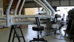
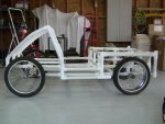
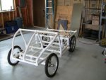
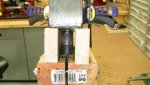
Once I got the front spindles sorted out, and the bearings for the front wheels, I couldn't resist putting all the wheels on and putting it on the ground.

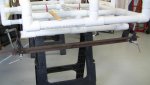
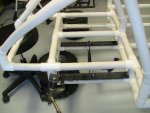
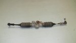
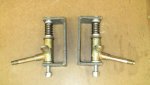
I had to extend one of the control arms coming out of the rack and pinion. My extension worked out pretty good but.....

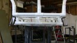
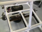
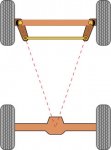
After I got the rack mounted in the frame, attached the control arms to the spindles, I gave the rack and pinion a turn and my wheels turn in the wrong direction! So either the rack and pinion is made to attach to the spindles in the front, or I have the rack in backwards. I really should have payed more attention when installing it. I was on a roll and was just trying to get it done.

I really don't think its backwards because the rack is angled towards the drivers seat. Wouldn't make much sense to angle the attachment point away from the steering column!
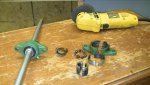
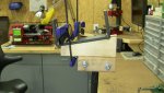
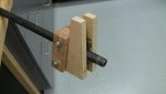
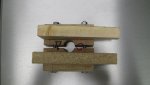
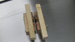
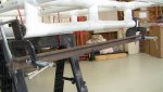
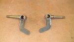
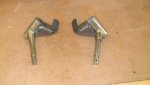
 

Attachments

  • IMG_2578.JPG
    IMG_2578.JPG
    57.3 KB · Views: 33
  • IMG_2576.JPG
    IMG_2576.JPG
    62.3 KB · Views: 31
  • IMG_2574.JPG
    IMG_2574.JPG
    65.2 KB · Views: 33
  • IMG_2573.JPG
    IMG_2573.JPG
    69.5 KB · Views: 33
  • IMG_2579.JPG
    IMG_2579.JPG
    74.7 KB · Views: 27
  • IMG_2581.JPG
    IMG_2581.JPG
    56.6 KB · Views: 34

OzFab

Well-known member
Messages
15,615
Reaction score
66
Location
Warwick Qld, Australia
Spin the rack 180*, that should help. Don't worry about the tie rods/rack ends, they're removable so, you can switch those...

If the rack is below the pinion, turning the pinion clockwise will result in the rack moving left.
If the rack is above the pinion, turning the pinion clockwise will result in the rack moving right.

Same concept as pointing a pitman arm up or down depending on the spindles
 

freqster

Member
Messages
68
Reaction score
0
Location
League City, Texas
Spin the rack 180*, that should help.
Well, the problem with spinning it is,
1. the splined stub that comes out of the rack that the steering shaft/knuckle attaches to, is angled towards the drivers seat. Spinning the rack would cause it to be pointing away from the drivers seat where it would be impossible to attache a steering knuckle.
2. The steering rack is not centered in the frame, so one arm is longer the the other. I don't think it is set up to be able to switch the arms in the rack.

So I think my best bet is to either switch the spindles so that the tabs are pointing towards the front, or make new tabs to weld on to the spindles. After that, I can mount the steering rack further up and attach it to the spindles.
 

OzFab

Well-known member
Messages
15,615
Reaction score
66
Location
Warwick Qld, Australia
No no, spin it 180* lengthways (so the right end becomes the left & vice versa). That will leave the knuckle in relatively the same position.

If you remove the rubber boots, you'll see that the rack ends screw onto the rack, meaning you can easily switch them
 

freqster

Member
Messages
68
Reaction score
0
Location
League City, Texas
No no, spin it 180* lengthways (so the right end becomes the left & vice versa). That will leave the knuckle in relatively the same position.

If you remove the rubber boots, you'll see that the rack ends screw onto the rack, meaning you can easily switch them

I understood what you are saying. The knuckle does not come straight out of the rack. The knuckle is pointing to the left, and towards the driver the way it is currently mounted. If I spin the rack, the knuckle will be pointing to the right, and away from the driver. I would need to add several little universal joints in the steering shaft in order to steer.

I will definitely try spinning it before I have to move the rack completely. I am all for less work on this.
 

Attachments

  • IMG_2557.jpg
    IMG_2557.jpg
    33.5 KB · Views: 16

Jim-L-L

New member
Messages
176
Reaction score
0
Location
South Australia
Well, the problem with spinning it is,
1. the splined stub that comes out of the rack that the steering shaft/knuckle attaches to, is angled towards the drivers seat. Spinning the rack would cause it to be pointing away from the drivers seat where it would be impossible to attache a steering knuckle.
2. The steering rack is not centered in the frame, so one arm is longer the the other. I don't think it is set up to be able to switch the arms in the rack.

So I think my best bet is to either switch the spindles so that the tabs are pointing towards the front, or make new tabs to weld on to the spindles. After that, I can mount the steering rack further up and attach it to the spindles.

How about flipping the rack like fabroman suggests and having it as RHD ? :thumbsup:
 
Status
Not open for further replies.
Top