2013 - AusEx (AmEx Replica)

Status
Not open for further replies.

OzFab

New member
Messages
15,615
Reaction score
8
Location
Warwick Qld, Australia
Steering

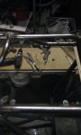
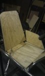
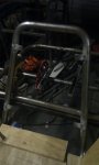
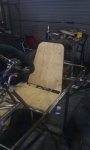
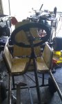
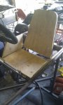
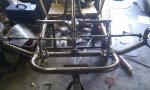
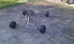
I've achieved a lot over the last few days; steering is all but complete, just needs a slight ackermann adjustment.

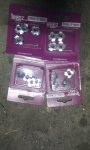
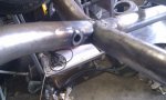
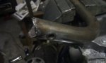
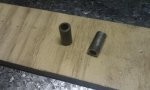
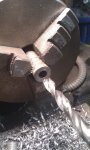
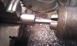
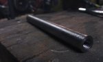
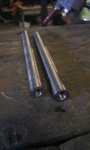
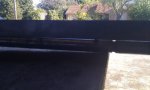
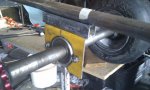
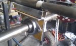
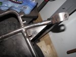
I picked up a pair of tie rods a few weeks ago, complete with right & left heim joints but, they were too short so, I cut them in half, threaded the ends & set about making extensions. Starting with a length of 1/2" round bar, I drilled & tapped the ends then, after fitting a nut to each of the ends, screwed the ends into the extensions to give me the correct length. Once finished & fastened, the nuts will not only lock the assembly together but will also act as an adjusting mechanism.

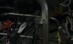
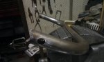
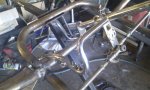
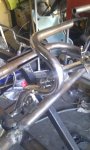
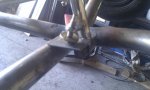
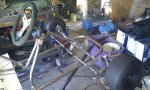
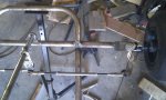
Now the steering column: As you know, it was too short so, once I made the extension (as seen in post #53) I first made two plug welds in each end then seam welded the ends... it's not goin' anywhere... As the standard tie rod mounting plate made the tie rods sit too high, I also axtended the pitman arm, now they sit level & straight.

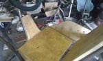
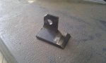
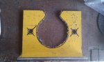
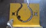
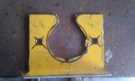
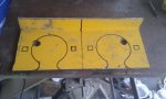
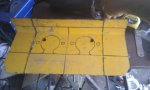
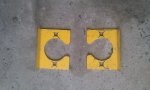
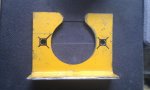
Having done all that, the steering works great but, the ackermann is out so, I also need to make a pair of adaptor plates for the spindles...
 

Attachments

  • IMAG0068.jpg
    IMAG0068.jpg
    104.4 KB · Views: 56
  • IMAG0071.jpg
    IMAG0071.jpg
    70.4 KB · Views: 46
  • IMAG0072.jpg
    IMAG0072.jpg
    45.3 KB · Views: 45
  • IMAG0073.jpg
    IMAG0073.jpg
    63.4 KB · Views: 52
  • IMAG0075.jpg
    IMAG0075.jpg
    45.4 KB · Views: 52
  • IMAG0081.jpg
    IMAG0081.jpg
    89.4 KB · Views: 150
  • IMAG0080.jpg
    IMAG0080.jpg
    80 KB · Views: 114
  • IMAG0077.jpg
    IMAG0077.jpg
    73.1 KB · Views: 50

OzFab

New member
Messages
15,615
Reaction score
8
Location
Warwick Qld, Australia
Rear Axle Bearing Mounts

For this build I decided to use flange mounts as opposed to pillow blocks due to the planned mounting setup so, as the mounting plates aren't readily available over here, I needed to make them.

Only a week ago, a buddy gave me a piece of 3mm plate with a 90* bend in it. At the time I thought "what would I use that for?" Can anyone guess :lolgoku:

I made a cardboard template of the shape & dimensions of the bearing plate which I transferred onto the steel plate. The only downside to the plate is it already had two holes in it so, I had to work them into the placement of the cutout.

Now to cut out round holes: As I don't have a hole saw capable of the job, I took two different approaches, just to find out which is easier:
-The first one I cut as much as possible out with an air hacksaw, then I had to file out the rest.
-The other one I drilled a series of holes around the edge, then ran the hacksaw through & filed out the rest.

Overall, I'd have to say that the second one was much quicker & easier.

The axle is now mounted to the frame; this is a temporary fit because I still need to finalise the design which for now, will remain a secret...
 

Attachments

  • IMAG0061.jpg
    IMAG0061.jpg
    73.8 KB · Views: 57
  • IMAG0060.jpg
    IMAG0060.jpg
    58.4 KB · Views: 60
  • IMAG0062.jpg
    IMAG0062.jpg
    63.1 KB · Views: 47
  • IMAG0059.jpg
    IMAG0059.jpg
    61.2 KB · Views: 45
  • IMAG0058.jpg
    IMAG0058.jpg
    55.9 KB · Views: 54
  • IMAG0083.jpg
    IMAG0083.jpg
    100.4 KB · Views: 160
  • IMAG0086.jpg
    IMAG0086.jpg
    72.5 KB · Views: 83
  • IMAG0085.jpg
    IMAG0085.jpg
    72 KB · Views: 90
  • IMAG0065.jpg
    IMAG0065.jpg
    82.8 KB · Views: 53
  • IMAG0064.jpg
    IMAG0064.jpg
    77.7 KB · Views: 57

KartFab

Active member
Messages
3,381
Reaction score
9
Location
Dallas, TX
Fabroman,

It looks like your kart is coming along nicely. Since I have the frame that is pretty similar to yours, I noticed something. My frame has some 1/8" bar stock welded from the frame towards the spindle brackets. You might want to add that for extra stability since the brackets are so far away from the tubing running lengthwise.

Now that I took that pic, I realized the frame is starting to rust... I need to hit it with the wire cup and paint it now.... posting is so much easier than actually working in the garage.... just one hour in the garage tonight.
 

Attachments

  • IMG_2369.jpg
    IMG_2369.jpg
    80.6 KB · Views: 88

Doc Sprocket

*********
Messages
15,677
Reaction score
10
Location
Ontario, Canada
That could also be done quite easily with an electric jigsaw (saber saw) with an appropriate blade. The air saw may have worked (I have one too) but for those that don't...
 

OzFab

New member
Messages
15,615
Reaction score
8
Location
Warwick Qld, Australia
Man does that look good! Whats the width of the axle? C to C?

Track (axle width, centre to centre) is 36"
Wheelbase is 48"
Exact 4:3 ratio

Looks real good. How are those valve springs working out? Did you put any weight on them to see how they flex?

TBH, it's been off the bench/trolley twice &, the last time, I did a bounce test & the front axle flexed more than the springs... :worried:

Fabroman,

It looks like your kart is coming along nicely. Since I have the frame that is pretty similar to yours, I noticed something. My frame has some 1/8" bar stock welded from the frame towards the spindle brackets. You might want to add that for extra stability since the brackets are so far away from the tubing running lengthwise.

It has crossed my mind & would work both aesthetically & cosmetically but, I wanna see how it goes without it first. Thanks for the tip :thumbsup:

Fan drilling ! old school but effective, about to do the same exept in 5mm plate for my rear flanges

Is that what it's called :lolgoku:

That could also be done quite easily with an electric jigsaw (saber saw) with an appropriate blade. The air saw may have worked (I have one too) but for those that don't...

I tried that too but, again, it was gonna take forever, not to mention it was a bit tight around the top near the bend... Drilling was by far the quickest method

Thanks for all the praise guys, it really does mean a lot :cheers2:

There probably won't appear to be a lot of progress over the next week or two as I plan to do things like the seat, pedals, engine mount & engine work next but, of course, there will still be updates

I made a gruesome discovery the other day: the 3/4" clutch I bought doesn't fit the 20mm crankshaft (obviously). I could've sworn I measured it but, anyway... Good thing I now have a lathe & can turn it down...
 

rwd4evr

Active member
Messages
174
Reaction score
51
Location
delaware
lookin good, thats about exactly what i should do to my steering hoop. what motor are you planning to run. acceleration isn't neck snapping but i'm getting about 40 mph at 6000 rpm on mine with 5:1 and i shouldnt be revving it over 4500 0r 5000.hmm,gotta get that two stroke duraforce rebuilt! the place i'm riding is wide open so accel isn't what i'm that worried about.
 

Nodroz

New member
Messages
1,071
Reaction score
0
Location
Belgium (Europe)
Once again, looks really professional and well made! Great job, Fabroman! ;)
And yeah, 3/4" inch just about 19mm. (19.05 to be exactly) ;) I wonde which engine has a 20mm crankshaft? Never seen those before...?
 

OzFab

New member
Messages
15,615
Reaction score
8
Location
Warwick Qld, Australia

OzFab

New member
Messages
15,615
Reaction score
8
Location
Warwick Qld, Australia
I didn't managed to do much over the weekend, between my daughter being here, trying to sort out my compressor plus one or two side projects & other distractions but, I did manage to get the wood for the seat squared away.

Obviously, the first step was to take some basic measurements, cut a piece of 15mm 5 ply to size &, for the seat, that was pretty much it. Then I cut 4 pieces of 25mm x 3mm flat bar 30mm long, drilled a hole ay one end, rounded the same end & tacked them in place on the frame. Once all 4 were in place, I used the holes as guides to drill the ply then drilled from the top side with a spade bit to create a rebate to house T nuts, pulled the T nuts into place & secured the whole thing into place with bolts from underneath.

As the backrest is angled on the sides, it was a tad more difficult so, I clamped it in place & traced around the frame then cut it out along that line; the corners still need a little work but, for now, it works. Then I followed the same procedure as the seat to secure it in place.

I've also cut out one of the sides & a piece for the steering hoop which I hope to finish sometime this week...
 

Attachments

  • IMAG0093.jpg
    IMAG0093.jpg
    53.3 KB · Views: 49
  • IMAG0098.jpg
    IMAG0098.jpg
    58.5 KB · Views: 49
  • IMAG0099.jpg
    IMAG0099.jpg
    56.8 KB · Views: 53
  • IMAG0089.jpg
    IMAG0089.jpg
    48.1 KB · Views: 63
  • IMAG0088.jpg
    IMAG0088.jpg
    72 KB · Views: 58
  • IMAG0090.jpg
    IMAG0090.jpg
    46 KB · Views: 58
  • IMAG0092.jpg
    IMAG0092.jpg
    52.3 KB · Views: 57
  • IMAG0104.jpg
    IMAG0104.jpg
    58.4 KB · Views: 68

OzFab

New member
Messages
15,615
Reaction score
8
Location
Warwick Qld, Australia
It's been almost a week & I've done next to nothing, what with the easter weekend & my compressor being out of action (AGAIN!), it's a bit of a chain reaction; if the compressor doesn't work I can't run my sandblaster so I can't finish cleaning the engine & I can't fit the clutch coz I have to pull the engine down to turn down the crank which means I can't mount the engine plate that's been sitting, waiting for a week...

So, instead, I've been slowly doing little things like finishing off the wood for the seat...
 

Attachments

  • IMAG0119.jpg
    IMAG0119.jpg
    75.3 KB · Views: 37
  • IMAG0117.jpg
    IMAG0117.jpg
    73.5 KB · Views: 25
  • IMAG0114.jpg
    IMAG0114.jpg
    67 KB · Views: 29
  • IMAG0113.jpg
    IMAG0113.jpg
    70 KB · Views: 29

OzFab

New member
Messages
15,615
Reaction score
8
Location
Warwick Qld, Australia
I also mounted the pedals: I took some 1/2" round bar & drilled out the centre to create a sleeve, then I drilled holes across the front bumper to house the sleeves & welded them in place from the inside of the tube so there's no clean-up needed.

After reattaching the bumper & bolting the pedals in place I found there was no back stop for the pedals so (as usual) I made some...

I cut a section out of some 1" angle, drilled a hole in the remaining part & there you go (ok, there was a bit more to it than that but, you get the idea). The drilled hole acts as a washer & holds the horizontal section in place which also rests on the front axle to create the stop. They still need a bit of dressing up but, they work
 

Attachments

  • IMAG0111.jpg
    IMAG0111.jpg
    81.9 KB · Views: 101
  • IMAG0110.jpg
    IMAG0110.jpg
    65 KB · Views: 68
  • IMAG0109.jpg
    IMAG0109.jpg
    44.6 KB · Views: 67
  • IMAG0108.jpg
    IMAG0108.jpg
    56.2 KB · Views: 69
  • IMAG0107.jpg
    IMAG0107.jpg
    67.1 KB · Views: 56
  • IMAG0120.jpg
    IMAG0120.jpg
    79.7 KB · Views: 71
  • IMAG0121.jpg
    IMAG0121.jpg
    86.5 KB · Views: 103
  • IMAG0122.jpg
    IMAG0122.jpg
    80.7 KB · Views: 84
  • IMAG0124.jpg
    IMAG0124.jpg
    67.3 KB · Views: 79

Nodroz

New member
Messages
1,071
Reaction score
0
Location
Belgium (Europe)
Woow, for some reason I missed this topic..


A lot has happened I see! Looking all very good as I expect! :) nice job

Sent from my GT-I8190 using Tapatalk 2
 
Status
Not open for further replies.
Top