Viper Offroad with full suspension project log.

Status
Not open for further replies.

rgvkid

Charlie Don't Surf!
Messages
267
Reaction score
1
Location
Los Angeles, Anaheim
Imo, You should never be over confident in a frame with a poor design. You or someone can get hurt if something fails. Always better to be a bit over built then under. I definitly Modelengineer on the double shear. It doesn't take that much time to add onto since you have everything in your shop. All you need is a 1/8 tab bent back to the cross support and welded in. You don't have to box in the sides of the tab above the shock but it woul dmake it so much stronger. You don't think there is going to be alot of weight in the front but when the rear end kicks up off a jump then all the weight will be shifted to the front. Plus gravity, There is a tremendous amount of weight which will be placed on those bolts so its always better off to use Grade 8 bolts especially if you are not double shearing.

Im posting a pic of some revisions to think of, which will give you a huge sense of confidence in your Kart and make the riding so much more enjoyable. If Not then your going to here us say," I Told You So". The triangulation support will help with the flex in the A-arm links, If it doesn't get in the way of your legs. The front bars will help with shifting form the suspenion working or if you take a bad hit into sopmething. You can remove the front 2 stright bars or better yet, leave them and triangulate the front bends to the bottom rail. This isn't that much work, but it will pay off later on. Trust me.

This is an Over sized go kart im working on right now, Triangulation is key to a greta frame.
 

Attachments

  • frontsusp3 Revision.JPG
    frontsusp3 Revision.JPG
    65.1 KB · Views: 196
  • K5 After.JPG
    K5 After.JPG
    148.9 KB · Views: 112
  • Blazer Crawler2.jpg
    Blazer Crawler2.jpg
    147 KB · Views: 160
  • K5 Door Guard1.JPG
    K5 Door Guard1.JPG
    136.9 KB · Views: 104

Moto909

New member
Messages
12
Reaction score
0
Location
hartley, ia
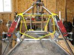
I now have the front suspension tacked together and I'm pretty happy with the results. I'm anxious to get it welded together solid so I can jump on it a few times to see how it performs.

You can see in the photos I also welded jam nuts to the suspension arms and installed the ball ends. I had to re-tap some of the nuts after welding because the threads got contaminated.

I also purchased a seat used for $60CAD. It's fairly large so I will have to modify the steering uprights and roll bar but I think it will be worth it for the extra comfort. Plus the price was good.


The front end looks kind of misaligned the two vertical bars and the hoop where your steering wheel will be is shifted to the side. It might just be where you attached the bars at. The first pic shows what im talking about.
 

xoltri

New member
Messages
75
Reaction score
0
The front end looks kind of misaligned the two vertical bars and the hoop where your steering wheel will be is shifted to the side. It might just be where you attached the bars at. The first pic shows what im talking about.

Good eyes, I noticed that as well. It is not critical that they are centered although it would look nicer. I tacked those in before I found the center of the upper bumper. It wouldn't take much to cut one of them off and have it match the other side, I may do this.

The curved upper support is directly centered, so it is just the vertical bars that are wrong. The steering wheel doesn't actually mount to that though, it is just for the suspension.
 

landy mad luke

New member
Messages
42
Reaction score
0
the kart is looking great and i cant wait to see it finished. rgvkid the "oversized gokart" looks like it would be a great Off topic thread. offroading is one on my other hobbies. How about a rite up?
 

Raywelder

Not an Adm¡nistrator
Messages
760
Reaction score
0
the kart is looking great and i cant wait to see it finished. rgvkid the "oversized gokart" looks like it would be a great Off topic thread. offroading is one on my other hobbies. How about a rite up?

Oversized cart?! Its an exocaged truck!
 

xoltri

New member
Messages
75
Reaction score
0
You guys have raised some good concerns with the strength of the frame so I have been playing with the free trial of SolidWorks to try and model the frame to see the best places for possible improvements. Here is a preliminary video with what I have made in the past 2 days. It shows a 400lb load applied to the top corner of the front bumper.

I hopefully plan on modeling the rest of the front suspension at least so we'll see what the computer says I should do for bracing. Plus it's a cool learning experience.

http://www.youtube.com/watch?v=3_glZ6v9F0U
 

theo

New member
Messages
872
Reaction score
1
I would like to see the bottom T arm of your front suspension made into a A arm. The fore and aft load on it is great and It will bend. You could have it attach on the out side of the C channel.

theo
 

rgvkid

Charlie Don't Surf!
Messages
267
Reaction score
1
Location
Los Angeles, Anaheim
Xoltri Thats a Sweet Program! That will help you alot with the design of the Kart. The fact that your taking in what alot of the viewers are saying, will help you make a way better Kart then what you would have expected. Better to keep having fun then to have fun worrying if something is going to break again. I look forward to what you come up with after taking the time to research your design with the program. Keep us posted.

Lets see some more animation. That gives a great perspective.
 

xoltri

New member
Messages
75
Reaction score
0
I haven't had a lot of time to work on it this week but I managed to get the TAV2 mounted to the engine which required a lot of grinding of both the engine and the mounting plate of the torque a verter to get it to fit. Otherwise I would have had to mount it vertically and I wasn't happy with that setup.

You can see some of the grinding in the photo. I also had to grind the spacer that goes on the crank shaft because my crankshaft is different than normal. But it fits now and seems to work good!


xoltri

New member
Messages
75
Reaction score
0
In the past few days I have lengthened the mid section of the frame and installed the seat rails to accommodate the larger seat. I will have pictures of this later as I may go to an auto wrecker to get adjustable seat sliders.

Today I took some photos of the steering as it sits now. I didn't want to get an expensive steering setup with a splined shaft and all the hardware so I went the cheap route.

I bought an old steering wheel from a GM truck for $10 and welded collars onto it on the front and back like so:


Then I bought a piece of 5/8 rod and drilled 2 holes in it to match the collars like so (only 1 visible):


This is cheap and it is removable, which is better than welding the steering wheel right on the shaft.

In the above photo you can also see the UHMW blocks that act as bushings for the steering shafts. Someone nice guy on another forum sent me these for free. They are a dense plastic. In the below photo you can see the bottom of the steering shaft, with a washer welded on as a stopper and a washer and cotter pin on the back to hold it in place. The tabs are fitted on but I have not welded them to the frame yet.


Finally here is the completed mock up. I still have to weld the pitman arm to the shaft as well, but I am waiting for the tie rods to be completed for that.


The nice thing about this setup is that it is adjustable up and down by moving the top bushing.
 

Brewcitytexan

New member
Messages
10
Reaction score
0
Location
Menomonee Falls, WI
Hey, the project looks great, thanks for soo many pics and and real build log, i was wondering whats the size of that cart? (how many feet long and how many feet wide?)
 

xoltri

New member
Messages
75
Reaction score
0
The frame is 77 inches long (6.5 feet) and 25 inches wide at the widest point. With the tires on it will be, according to the plans, about 45 inches wide.

Love your signature BTW. :thumbsup:
 

theo

New member
Messages
872
Reaction score
1
xoltri, how is the build coming along? What size and wall thickness is the tubing used?

theo
 

xoltri

New member
Messages
75
Reaction score
0
Hey it's going good, little slow lately due to time constraints. I should have some new pictures up today, I have 'permission' to put in a couple hours in the garage. I have the seat mounted on adjustable rails and have been working on the live axle.

The kart is 1" x 1/8" wall tubing for the most part. There is also some 3/4" x .065" wall tubing for the upper portions.
 

xoltri

New member
Messages
75
Reaction score
0
Here are some more photos of the project. I have finished the live axle, which involved modifying a solid ground and polished 1" bar. I could have bought a keyed axle but it was twice as expensive as the non keyed one.

Basically I took the keystock, traced the outline of it on the axle, and then ground it out with an angle grinder. I found it helpful to use a zip disc to get the outline ground out and then use a normal disc to grind out the remaining material out of the center. It didn't take that long to complete. I only ground the keyway 7 inches on each end as that is all that is required.


You can see that I also drilled and tapped a hole so that I can fasten the hubs to the axle without them falling off.


I found out that I bought the wrong axle bearings so I couldn't mount the bearing hangers to the frame, so that will wait for another day.
 
Status
Not open for further replies.
Top