Viper Offroad with full suspension project log.

Status
Not open for further replies.

xoltri

New member
Messages
75
Reaction score
0
A couple years back I purchased the plans to build a Viper Offroad go-kart and have been slowly plugging away at it.

I had been keeping my progress log at the official forums for these plans but recently it appears that all the log-ins got disabled so I am going to move my progress log here. It's fairly long so far but I'm trying to keep a complete log for other people's future reference.

I started this back in July of 2006. I knew it would take a long time back then, and now almost 3 years later I am starting to make real progress. Of course during this time I have done full landscaping my house, built a 22x24 garage and done a bunch of other renovations. Now that the garage is built I should make some fast progress now.

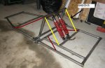
The go-kart is made for a 5-8HP engine. It has front and rear suspension. I bought the plans from easykarts.com. They are fairly complete, but they only give you access to the online plans for a certain amount of time so there may have been updates since I got my copy.


xoltri

New member
Messages
75
Reaction score
0
Before I started the go-kart I built myself a workbench, from free plans. It has served me very well for the past couple years. I made a few modifications, such as installing the overhead light and powerbar, vice, and the peg-board at the back.


xoltri

New member
Messages
75
Reaction score
0
Also I acquired a bunch of tools to work on this project. The plans say that you could build this with a hack saw and a hand drill but it is fairly ridiculous to think that this would be a viable solution. Get the right tools to do the job.

Cutoff saw ($100 CAD used)


6" bench grinder. I wish I would've bought an 8" as this one bogs down a lot.


Drill press and cross vice ($200 CAD). A hand drill for drilling steel is a waste of time. It's inaccurate, slow, and you will wreck drill bits. This setup works awesome.
 

xoltri

New member
Messages
75
Reaction score
0
When I started this project I didn't own a welder so I spent some time making all of the little parts according to the plans with the tools I had available.

The plans give you two options for the spindle cradles, one is to bend them to shape out of 1 1/4" x 1/4" steel, or cut and weld them. I chose the latter as I do not have the capabilities to accurately bend 1/4" steel bar. There are 14 spindle cradles total, as they are used as hinges and other things since this is a full suspension kart.

Cut, drill and grind the tabs:


Cut and grind the flat backing bars:


Test fit:
 

xoltri

New member
Messages
75
Reaction score
0
Since I did this work on the spindle cradles I purchased a welder for $300CAD with shipping on Ebay.


It is a 90 amp flux core welder that is convertible to MIG if you get the regulator and gas bottles. The maximum thickness this welder is rated for is 3/16" with flux core wire, but these cradles are 1/4", so I was a bit concerned that they would not be strong enough.

To help I ground a V channel in the pieces on both sides. You can see this in this picture.


I messed up on this piece unfortunately but this gave me a good opportunity to test my weld, so I hit the piece with a 5lb sledge and it withheld great.


I have only used this welder once before this picture was taken. It is super easy to use.

Here are two completed cradles. They are turning out good and I am getting cleaner at welding which means less grinding.
 

xoltri

New member
Messages
75
Reaction score
0
Here are some other misc pieces I have fabricated.

Brake and gas pedal's out of 3/8" steel. I may get some actual pedals or weld some type of diamond plate to dress these up a bit eventually. They were bent using my vice and the back end of a wrench as a lever.


Spindle arms and pitman arm:


Throttle and brake rods. Those are I believe 1/8" holes drilled into these rods for cotter pins. Without a drill press these would've been almost impossible to get accurately.


Guide tabs for the throttle/brake rods:


Pedal tabs. These provide a mounting point for the throttle/brake rods.
 

xoltri

New member
Messages
75
Reaction score
0
The plans call for 1 1/8" x 0.083 wall Drawn Over Mandrel tubing. I sourced some of this tubing locally and it would've cost me over $300. This was simply too expensive, and I believe that DOM tubing is overkill for this application.

So, as an alternate I found a source for Electric Resistance Welded tube. Basically DOM tube is ERW tube that has been cold worked to make it more uniform and stronger. But the ERW tube was only $100 for the same length of tube so it is much more cost effective.

Also I was not able to find 1 1/8" x .083 ERW tube locally. I created a spreadsheet (available here) that allowed me to find a comparable replacement. The tubing that I purchased was 1" x .12 wall ERW tubing. Based on my spreadsheet it will be about 8lbs heavier than the recommended tube and at least just as strong. The weight penalty sucks but I'll just go on a diet and make up the difference. :p

To go along with this tube, a while back I purchased a tubing notcher on eBay for $45US. It will cut notches in the end of the tubing so that it fits together properly for welding.
 

l0ll00l

New member
Messages
81
Reaction score
0
Location
San Antonio, TX
Very nice work so far! It's great to see the right tools being used in a build. Always makes things go so much more smoothly.
 

xoltri

New member
Messages
75
Reaction score
0
I have also purchased the 4 shocks necessary from Ebay for $120us total including shipping.


The plans call for some of the frame sections to have bends in them. Bending tube is not easy, especially since these bends are 2" radius bends which is pretty tight. I did buy plans for a tube bender however this is cost prohibitive as the dies are really expensive ($150-180US) and I would probably only use the tube bender on this one project.

I have been trying to find a local shop who can make these pieces for me so we'll see how that goes. I just have to get some diagrams drawn up first.

You can sort of see on this picture a few of the bends.


The main frame, as stated above, is being built using 1" x .12 wall ERW tube. These other tubing parts, including the bent pieces, will probably be made from 3/4" x .065 wall tube. So it will be lighter and cheaper.
 

rgvkid

Charlie Don't Surf!
Messages
267
Reaction score
1
Location
Los Angeles, Anaheim
looks great! The welds look good but don't be afraid to turn up the heat, especially if you are trigger spot welding and with that thickness of material. Cant see it in the pic, but try not to grind to much of the bead down on the outside of the spindles, The inside looks good and its just enough to clear the rotating braket. Good luck.
 

xoltri

New member
Messages
75
Reaction score
0
Today I finished welding together all of the spindle cradles minus one since I need more material.

Also I started on the rear section of the frame. The plans call for a few of the tube lengths to be 21 3/8" long. However to accommodate the notching of the tube you must account for 1/4" on each end, so I made the pieces 21 7/8" long.

I tried a few times to get the notcher to work properly. At first I did it with a hand drill however I ended up wrecking the hole saw because it is impossible to control the RPM's. I purchased a new hole saw and abandoned the notcher and tried it on my drill press with the cross vice. However the drill press is very sensitive to lateral pressure and it was cutting all over the place and a couple times the press fit chuck fell off.

The solution was to use both the drill press and the notcher. This lets you control the RPM's (500rpm) and provide lateral stability.


Result:


Test fit:
 

xoltri

New member
Messages
75
Reaction score
0
I welded together the rear porch tubing yesterday and today. This is the section with the engine and rear axle, and it will connect to the front section with hinges and hydraulic shocks.

I brought it in the house to show my wife and neglected to tell her that it was still hot and she burnt her fingers, but just barely. Still, :oops:

Construction is going pretty smooth, the notcher is working great and I am happy with the way the welder is working.

It helps to have 4 of these welding magnets which help hold and square the tubing for tack welding:


xoltri

New member
Messages
75
Reaction score
0
I (mostly) finished the mid section tubing today. It was a bit challenging to get the front pieces angled properly. To square it up I made sure that the distances at the red lines were equal and the distances at the yellow lines were also equal.

I also had to use my tube notcher at a 15 degree angle to get a good fit.


The magnets worked good to hold it in place but they are not precisely accurate so measuring and re-measuring was the only way to get it all squared up.


xoltri

New member
Messages
75
Reaction score
0
Today I welded the hinges on the two frame sections, and built the frame and hinges for the rear suspension. I do not have bolts to install the shocks yet so they are just held temporarily for the photo.

This is going faster than I thought! I need to pick up more material now.


rgvkid

Charlie Don't Surf!
Messages
267
Reaction score
1
Location
Los Angeles, Anaheim
IMO this is what i would do to add strength to the design. If you go exactly off the design, your upper shock mount bar would be very weak and could have a higher potential of getting hurt. The frame and stress points should be triangulated which well help with frame structure and less flexing which could lead to bending the frame while off roading or even bumpy streets. Better to let the suspension do the work and not the frame. Putting the shocks out to the furthest rails on the swing arm would help support the rear alot better, especially with the weight of the motor. You might have to move some stuff over, but you will have a much more superior swing arm. Like the truck in the pic.
 

Attachments

  • rear_susp 1.JPG
    rear_susp 1.JPG
    54.2 KB · Views: 241
  • 1999-ford-ranger-4x4link-the-project-begins.jpg
    1999-ford-ranger-4x4link-the-project-begins.jpg
    40 KB · Views: 369
Status
Not open for further replies.
Top