Manco vortex go kart

Possom Point

Well-known member
Messages
246
Reaction score
357
Location
Virginia
Starting a different style project this time….
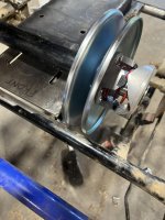
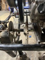
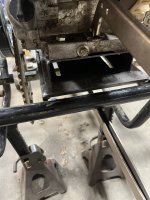
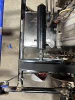
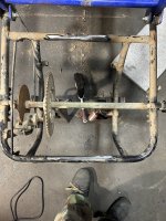
A Manco (American Sportworks) vortex go kart. We picked this up a couple years ago that was in decent shape for $400. It was running when we got it and has been in “storage” since then. As always the seat was shot, rotten and torn up front tires kept needing air. Had the stock 6.5hp Subaru engine. These are great karts for 2 people because of the full suspension and they ride great too. So I have been tinkering with the idea of mounting a GX390 big block on it for a while, looking a it. Walking around it, touching it and so on.
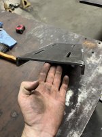
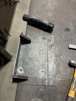
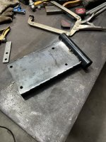
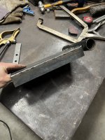
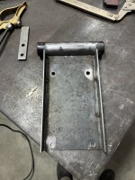
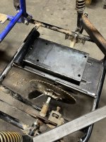
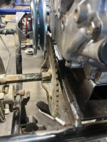
So I decided to commit to it and took many many measurements before I started cutting and did my best to not chop the original motor mount and pipes so I could re-weld it in case this didn’t work out.
 

Attachments

  • IMG_5332.jpeg
    IMG_5332.jpeg
    4.7 MB · Views: 20
  • IMG_5324.jpeg
    IMG_5324.jpeg
    4.2 MB · Views: 19
  • IMG_5333.jpeg
    IMG_5333.jpeg
    2.9 MB · Views: 18

Possom Point

Well-known member
Messages
246
Reaction score
357
Location
Virginia
I drew up a motor mount plate for the GX390 mounting slots and cut it out on my plasma, then welded flat bar on each side to stiffen the mount. So where I’m at and probably will be for a little while is making a Torque Converter mount like the original but obviously bigger. The tube measured 1” 5/8 OD with 1” 3/8 ID for the bearings. I will need to figure out the tube length for the jackshaft……. So more brain storming to come. If anyone has any suggestions please don’t hesitate to post.
 

Attachments

  • IMG_5336.jpeg
    IMG_5336.jpeg
    4 MB · Views: 4
  • IMG_5337.jpeg
    IMG_5337.jpeg
    1.8 MB · Views: 5

panchothedog

Well-known member
Messages
2,788
Reaction score
3,733
Nice work on the motor mount plate. Looks very professional. I have a Manco intruder kart. Looks a lot like yours. Big kart. Wheelbase is 67 or 68 inches. By far the best riding kart of the 4 I have. Good luck with your build. A 390 should move it along quick like.
 

Possom Point

Well-known member
Messages
246
Reaction score
357
Location
Virginia
Got this cut out today , drew it out up on Fusion 360 and cut it on the plasma table.
so this will be a Gen 1 mount, given that this is a trial and error task, I may have to make the mount bigger to fit the tube.
as of now it’s in the flat and will be fitting it up soon to weld it. The tube in the back was the one that got cut off the green dingo I did a while back.
 

Attachments

  • IMG_5340.jpeg
    IMG_5340.jpeg
    2.7 MB · Views: 5

Possom Point

Well-known member
Messages
246
Reaction score
357
Location
Virginia
Don't underestimate the torque damage that 390 can do. I had lotsa problems with engine/mount and jackshaft getting moved by the chain pulling on it. I added struts from the mount to the frame, finally. Problem solved! Thats even before the 390 became "unstock".
I made this mount out of 11ga steel, I want to say the typical Manco mounts are 12ga only 0.20” difference in thickness, do you think I should go to maybe 3/16”? The main plate is all 1/4” steel just for reference.

This is a very good point to consider making this before I get to far………
 

Master Hack

Well-known member
Messages
4,037
Reaction score
6,418
Location
Mountain top Labratory
The material is probably fine. Mine is built differently, but the result is likely the same.
The problem wasn't the plate bending, but sliding backwards. The clamping force of the bolts that attached the engine and adjustable mounting plate was not enough to keep it from moving. Every time it moved the chain was loosened up.
The "strut" thingys solved the moving problem. See pic below.


IMG_4249.jpeg
 

Possom Point

Well-known member
Messages
246
Reaction score
357
Location
Virginia
The material is probably fine. Mine is built differently, but the result is likely the same.
The problem wasn't the plate bending, but sliding backwards. The clamping force of the bolts that attached the engine and adjustable mounting plate was not enough to keep it from moving. Every time it moved the chain was loosened up.
The "strut" thingys solved the moving problem. See pic below.


View attachment 150051
Ive had this happen to me before on another kart and couldn’t figure out what it was. Crazy has those bolts don’t hold down with that much clamping force.

I see why you’re called master hack!!! That is a superb mount you made there with the heim joints.
also it looks like you have additional tightening setup? I see some all thread welded to some flat bar.
 

Master Hack

Well-known member
Messages
4,037
Reaction score
6,418
Location
Mountain top Labratory
also it looks like you have additional tightening setup? I see some all thread welded to some flat bar
That was the first attempt at an adjuster. I had a piece of 3/4 all thread. That engine/mount thingy can't move around that, can it? No but it can deform that .120 wall square tubing. The flat bar ya see was to double the thickness at those 2 adjusters.
The heim joints don't allow the mount to move, unless l want it to.
 

Possom Point

Well-known member
Messages
246
Reaction score
357
Location
Virginia
I also had to beef up my motor plate with my 301. I doubled the floor plate and the runners down the side. Also had to weld in support legs to another part of the frame.
My new project also ripped the motorplate off. Same treatment.
That’s kinda what I’m thinking now, maybe some gussets or bracing for the mount once I get it welded and look at it some more.

So on the tube, most all the mounts I see they are just welded in 4 places about an inch to inch and a half. I’m hoping I won’t have to brace the tube in anyway but again I won’t know until I get things welded up.
 

Possom Point

Well-known member
Messages
246
Reaction score
357
Location
Virginia
That was the first attempt at an adjuster. I had a piece of 3/4 all thread. That engine/mount thingy can't move around that, can it? No but it can deform that .120 wall square tubing. The flat bar ya see was to double the thickness at those 2 adjusters.
The heim joints don't allow the mount to move, unless l want it to.
I can imagine 3/4” all thread will deform tubing without a doubt, a lot of strength in those threads than ppl think.
 

Possom Point

Well-known member
Messages
246
Reaction score
357
Location
Virginia
At this point tonight I welded the mount up solid and got the tube tacked in place for now. I looked at another Manco go kart that has a gx390 on it and copied the measurements from that to this mount. This particular kart had the tube offset from the main plate which is different than what I’m use to and roughly centered to the edge of it, most of them are just welded to the top of the plate. I need to do a mock up this week with the engine on it as well as the clutch and driven unit to get the “correct“ belt length which I’m going to my best to make sure it’s close to possible as a “stock” 40 series belt, meaning a more common length size.
 

Attachments

  • IMG_5364.jpeg
    IMG_5364.jpeg
    2.5 MB · Views: 10
  • IMG_5365.jpeg
    IMG_5365.jpeg
    2.1 MB · Views: 6
  • IMG_5366.jpeg
    IMG_5366.jpeg
    2.5 MB · Views: 8
  • IMG_5367.jpeg
    IMG_5367.jpeg
    2.4 MB · Views: 8

Possom Point

Well-known member
Messages
246
Reaction score
357
Location
Virginia
Ran into a pretty bad problem When I mocked up the driven to the jackshaft plate and loosely put the motor on. Everything was to close together, after looking at it for a little bit I realized the mount or mount needed to be flipped 180 degrees. I missed this when I put it on. Also the driven was waaaayy too close to the frame for comfort. Basically the engine was not far enough over to give it clearance, this is why we “tack” things first. After that I roughly remounted the parts and now my dilemma is I believe the jackshaft will be sticking out to far and bend under the torque of the motor.

before cutting out the mount plate
 

Attachments

  • IMG_5380.jpeg
    IMG_5380.jpeg
    2.4 MB · Views: 8
  • IMG_5381.jpeg
    IMG_5381.jpeg
    1.8 MB · Views: 8
  • IMG_5382.jpeg
    IMG_5382.jpeg
    1.7 MB · Views: 8

Possom Point

Well-known member
Messages
246
Reaction score
357
Location
Virginia
I also noticed that the holes now do not line up with the slots in the plate. Not a big deal, drill a hole about an inch past the slot and cut out the remainder with a cut off wheel, pretty simple.
As far as the jackshaft setup, should I use pillow block bearings to reinforce the driven Side? So it doesn’t bend under load.
These are pics after I remounted everything.
 

Attachments

  • IMG_5385.jpeg
    IMG_5385.jpeg
    1.8 MB · Views: 7
  • IMG_5386.jpeg
    IMG_5386.jpeg
    1.7 MB · Views: 7
  • IMG_5387.jpeg
    IMG_5387.jpeg
    2.1 MB · Views: 7
Top