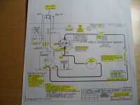
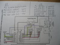
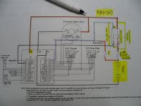
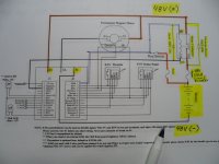
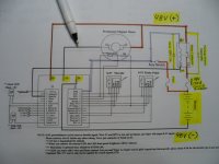
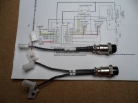
Ok now, let's go back to the diagram
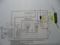
...& take a look at where that resistor & diode go

The
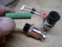
pre-charge resistor "goes" across (connecting) the main contacts, on the contactor
(this allows's a small amount of current to go "cross" the main terminals, which pre-charges the capacitator's in the controller)
...so, that the capacitators don't get "over loaded" by a huge inrush of current, when the contactor "connects" the main contacts.
The
diode "goes" across the contactors, coil terminals (the coil is a small electric switch, within the contactor, that when activated, turns on/connects the main contacts)
...this diode, is supposed to block any "feedback" current, that may occur, when the contactor is turned off
I positioned them (resistor & diode) on the diagram, next to where they go
...& also, used a highlighter to "highlight" 'em

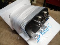
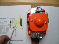
Below is a pic of the contactor, with the pre-charge resistor & diode installed
...& ima pointin' ta where it goes
* This contactor has a 400A rating (to match the controllers 400A rating) & a 48V coil (for use with a 48V system/batt pack)
Remember, the
J1 connector is just for connecting the (2) indicator LED's & the negative (-) for the contactor's coil
It's the
J2 connector, where most of the "action" happens

So, we'll start with the
J2 connector's, pin #1 labeled
PWR.
This where the key switch connects pack voltage (~48V in this case) to the contactors coil positive (+) & to "turn on" the speed controller
...so, that when the key switch is activated, it supplies 48V (+) to the contactor's (coil) & also, to the controller (white wire)
Then, pin #3 labeled
Main RLY on the J1, connector supplies the negative (-) to the contactor's coil (black wire)
* Notice, once the key switch is "activated" the contactor has a constant power supply, from the batt pack (orange wire, designating "high voltage (from batt pack to the switch) thru the white wires (that connect the positive (+) from the switch to the contactor & speed controller)
...so, the negative (-) side (black wire) is how the contactor "cuts" the power, to the controller (like if you reach the undervoltage setting etc.)
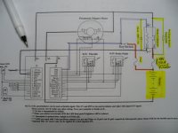
Also, in this pic, I highlighted the battery pack, circuit breaker (resettable "main" fuse)
...& a fuse (5A) (this protects the controller & the contactor's "signal power" circuits)