Hell-raiser 72V Electric Racing Kart

Functional Artist

Well-known member
Messages
5,350
Reaction score
2,836
Location
Toledo, Ohio
Getting the cut-to-length keystocks is what I do also, but why are the whole 12" long pieces mounted on that rear axle?
Must be an optical illusion 'cause I don't use "keys" during "mock ups" :unsure:

IMO, Ya don't need a "key" (connecting the axle to the brake drum) until the brake drum (or sprocket or wheel) actually needs to affect the rotation of the axle. ;)

Um...no comment on the Super Heavy Duty brake band mount
...or the adjustable rod to brake band connector 🙃
 

Kartorbust

Inmate #627
Messages
4,403
Reaction score
843
Location
Utica, NE
Never thought about keyways getting dinged up, requiring some filing to fix it. I can see where a piece of 1/4" keystock sticking out 1/8" from the keyway would take a hit that would protect the keyway.

After seeing Greg from Red Beard's Garage wreck a key way from too much torque snapping and destroying the shaft key way, it's best to run longer keys than just enough to hold everything in place.

Splines would be better, but no one has the tooling to do all that and getting it custom done isn't cheap.
 

Functional Artist

Well-known member
Messages
5,350
Reaction score
2,836
Location
Toledo, Ohio
Throttle
Ima gonna use the simplest & cheapest (low cost not low quality) option for a throttle, on an electric kart, the thumb throttle (under $10.00)
https://www.ebay.com/itm/403498100715?hash=item5df25c67eb:g:1S4AAOSwntBiF1VS&amdata=enc:AQAHAAAA4F9eZt5zYWq1fEhTZxuSPvhU0faEcbmtbd2CZrgNYXbKZZVcApEW0OovDsW18VjfArZzXvYjd+qxApqpWjrGGlWgcwQJ7TEOdW95BSfaJRemqS6iDpMckpgNNR5C8FbGtiD20HYQJxxF5Pl/fXoqTuc+nay8IsRp17/RBsO9RVQ4VQNQqwSCaywzUaeJ2Iv63TksGsbrbzgyRlTZgrkKeCn7PmalnuWux5q9uDVshwt16pEpOa1vy0o9dZbDxXBeSyj1XA9NICeY6PNNuj/Z9Cicdu123q7OMK9xtbjv4UZC|tkp:BFBMiPjj95pg
...but, since we are using pedals, we need ta get creative

* Most thumb throttles fit standard 7/8" dia. handlebars
...so, it'll fit on a piece of 7/8" dia. pipe (welded on pretty much anywhere)
...& be can actuated by a cable, connected to the pedal

So, I found a "safe" place ta mount a thumb throttle (under the front of the seat)
...& welded a little (~3") piece of piece pipe, ta the seat mount (in line with the throttle pedal)

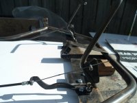
Throttle linkage
Next, I made up some cable guide/mounts (cut up the brake, off an old 10 speed bike)
...& installed a piece, in front of the pedal (bolted on so, it's adjustable)
...& welded another piece on, just in front of where the thumb throttle will be mounted (no need for "dual adjustment")

Then, used a small section of brake cable (also off the old 10 speed bike) ta connect the pedal to the thumb throttle

Warning
...pic sucks (lighting or glare or something)
SAM_4351.JPG

Here is a better pic of the front connection
...notice the "adjustable stop" ta keep the pedal from coming back too far
SAM_4355.JPG

...& here is a close up, of the rear connection
SAM_4353.JPG
 

madprofessor

"Loose Cannon Creations"
Messages
2,899
Reaction score
962
Location
Jacksonville, Florida
How does the effective degrees of rotation on an electric thumb control compare to the effective degrees on an electric foot pedal?
IOW: Does one of them require less degrees of rotation (ex. 90-degrees) from stop-to-full than the other (ex. 60-degrees) ?
 

Functional Artist

Well-known member
Messages
5,350
Reaction score
2,836
Location
Toledo, Ohio
How does the effective degrees of rotation on an electric thumb control compare to the effective degrees on an electric foot pedal?
IOW: Does one of them require less degrees of rotation (ex. 90-degrees) from stop-to-full than the other (ex. 60-degrees) ?
I'd say a thumb throttle & the pedal "style" throttles, both have about the same amount of "travel"
...probably ~1"

While were talkin' about throttles, check these out ;)

Cable Pull Throttle (~$25.00)
Heavy-duty linear cable pull throttle. Great for converting scooters, motorcycles, dirt bikes, mini bikes, and go karts from gas to electric power. Made from tough glass fiber reinforced nylon. Body dimensions are 5-1/8" long x 1-1/4: wide x 3/4" high. Body has four 0.16" ID (4.1mm) mounting holes that #8 machine screws fit through. Pull cable is 6" long and has a 0.06" (1.5mm) diameter. Cable pull distance is 1". Variable speed throttle is at zero when cable is released and at full when cable is pulled out 1". Cable has stopper that prevents it from being pulled out of the body. 35" long electrical cable. Wire colors: red, black, and white. White wire connector mates with item # CNX-52.
Item # THR-99


http://electricscooterparts.com/throttlesstandard.html
 

Functional Artist

Well-known member
Messages
5,350
Reaction score
2,836
Location
Toledo, Ohio
Floor board

I welded (4) tabs onto the frame (for mounting the floorboard)
...& the pedal mount will act as a full-length front tab

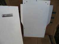
Then, used a piece of cardboard to trace a floorboard
...& cut 'er out

Then, used it as a template to trace "the pattern" out on a piece of steel

I harvested the steel (~16g) off the front of an old Kenmore refrigerator door (has a texture "punched" right into the steel)
...& thought, it may work good for a floor board ;)
SAM_4358.JPG
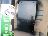
* After cutting 'er out
...drilling the bolt holes
...adding a small "kick up" on each side (ta give 'er some extra ridgity)

Then, cleaned 'er up a bit
...& gave 'er a good coat of Black Appliance Epoxy Paint (it was a refrigerator door don't ya know) ;)
SAM_4359.JPG
 

Functional Artist

Well-known member
Messages
5,350
Reaction score
2,836
Location
Toledo, Ohio
Mounting the seat

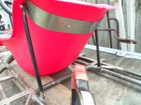
The seat Ima using is just some kind of HD plastic (from BMI Karts)
...so, I made a "wrap around" re-enforcement bracket, to strengthen, where the upper mounting bolts will attach
(a piece of ~2" wide 16g steel, with (4) bolts "strategically" spaced out)

* Ima thinkin' this concept should "spread out" the "dynamic stress" (all across the top of the seat)
...that the (2) "outer, top bolts" would have had to "deal with" otherwise, on their own :cheers2:

As for rear of the seat mounting "connecting rods", I used a piece of ~1/2" steel tube with the ends "flattened" (from old riding lawn mower)
...cut 'er in half
...flattened the ends (in the press)
...& then, drilled mounting holes, in the freshly flattened ends
SAM_4301.JPG
Welded a couple of "tabs" onto the frame (being sure everything clears the batt pack & the motor)

After mounting, the seat, I sat in it
...& tried "shifting around" a bit

I must say, it feels pretty solid :)
SAM_4311.JPG
 

Functional Artist

Well-known member
Messages
5,350
Reaction score
2,836
Location
Toledo, Ohio
There was a Alltrax 4834 speed controller that came with the ME0708 PM motor that I bought (that was supposed to be a ME0709)

I tested the motor (seems to work fine) :thumbsup:
...& now, I'm trying to "bench test" this controller

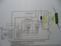
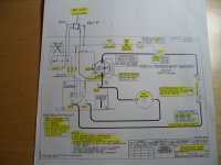
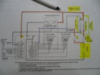
I downloaded the wiring diagram, from Alltrax (even printed a few copies to draw on & make notes)
...& it seems pretty simple :wai:

So, it looks like each time the accelerator is activated, this "foot switch" activates the contactor
...& also, turns the speed controller "on"

Then, each time the accelerator is released this "foot switch" deactivates the contactor
...& also, turns the speed controller "off"

* One thing, I think Ima gonna change/deviate from, the diagram is where it shows a "foot switch" (incorporated in with the throttle)
It's in the circuit between the key switch & the controllers KSI (tab #1) & also, the contactor

* Also, the Alltrax AXE 4834 specifications say that these controllers are compatible with different throttle inputs

Throttle Input:
  • ITS (inductive)
  • Resistive 0-5K ohm (+/-10%) (2-wire and 3-Wire)
  • Resistive 5K-0 ohm (+/-10%)
  • 0-5Volt
  • 6-10Volt
The LED Blink Codes occur at power up, the number of green blinks indicates the throttle configuration:
  • 1 Green LED flash = 0-5 kohm resistive
  • 2 Green LED flashes = 5K-0 ohm resistive
  • 3 Green LED flashes = 0-5 Volt
  • 4 Green LED flashes = EZ-GO inductive (ITS)
  • 5 Green LED flashes = Yamaha 0-1K ohm resistive
  • 6 Green LED flashes = Taylor-Dunn 6-10.5 Volt
  • 7 Green LED flashes = ClubCar 5k-0 ohms, 3-wire throttle
Ima gonna use a simple 0-5V (hall effect) thumb throttle
...but, it requires a 5V power supply
...so, I added a (48V to 5V) DC to DC convertor, to the diagram & the throttle too

** Another also,
I notice on the diagram it says "* Note for motorcycle use: motor wires need to be 3' to 5' long. Coil extra wire into 4" loops & zip tie together."
...I wonder why?
SAM_4348.JPG
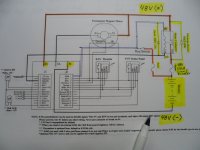
So, I connected the controller as per the diagram (pic in first post)

Then, when I switched it "on", the green LED light flashed (3) times
...according to the manual, this indicates that the throttle is configured for use with 0-5V
...then, it stayed on steady, green
Normal display status:
  • Solid Green: Controller ready to run
  • Solid Red: Controller in programming mode (using Controller Pro)
  • Solid Yellow: Controller throttle is wide open, controller is supplying max output, and is not in current limit.
But, when I activated the throttle, nothing happened (no buzz, no hum, no pop, no nothing) :huh:
 

Functional Artist

Well-known member
Messages
5,350
Reaction score
2,836
Location
Toledo, Ohio
To try-n-figure this thing out, I connected the controller to the computer (with a USB to SERIAL cable)
...& a 12V battery, to check the programming/settings

In the first tab
Control Panel
Settings

Max output was set @ 100%
Under-voltage @ 20V
over-voltage @ 55V
Throttle up rate 5
Throttle down rate 5
Brake Current 0% (no regen)
Top Speed 100%


Switches
The only option, that I noticed that was "checked", was High Pedal Disable

* Everything looks OK :thumbsup:
SAM_4362.JPG
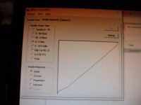
The second tab
Throttle Response
Throttle Sensor Type was set @ 0-5V
Throttle Response was set @ Linear (the other options were S-Curve, Progressive & Inductive)


*Seems to be set for, use with, a 0-5V throttle :cheers2:
SAM_4363.JPG
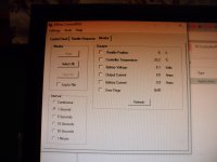
The third tab
Monitor

* It didn't really tell us much (because nothing was actually happening, like controlling a motor)
...but, there didn't seem to be any "Error Flags" either :)
SAM_4364.JPG
* Well, I guess a call to Alltrax Tech Support, is next. :popcorn:
 

Functional Artist

Well-known member
Messages
5,350
Reaction score
2,836
Location
Toledo, Ohio
I called Alltrax Tech Support & explained the situation.

The tech asked the typical "by the book" questions like, have you tested the throttle & contactor & F/R switch & even the motor

I said yes, all components tested properly, except the controller & reminded him that I was doing a "bench test"
...so, (as of right now) I only have the batt pack, throttle & on/off switch connected (for this test)

Well, he says, if you connect the M- cable together with the B- (bypassing the controller) & the motor "spins"
...then, most likely the controller is "bad" :(

Yup, I tried it ;)
...& the motor just about jumped off of the work bench :eek:

* So, I don't get it
...the indicator light seems to "work properly"
...& even in the programming, everything seems OK
...but, it still doesn't work????? :mad2::furious2:

Ima gonna order a Kelly controller :2guns:
...BRB :popcorn:
 

Functional Artist

Well-known member
Messages
5,350
Reaction score
2,836
Location
Toledo, Ohio
So, on the Kelly Controls web site & l looked at the motors first (to see what they recommend for a ME0708 motor
https://www.kellycontroller.com/shop/

Here is the motor info:

Mars 0708 (Etek-R Comparable) Brush-Type Permanent Magnet DC Motor

This is a Brush-Type, Permanent Magnet DC motor with very high efficiency. Capable of 4.8 KW continuous and 15 KW for 1 minute. For voltages from 12 to 48 VDC input and 100 amps continuous. Designed to be an Etek motor replacement.
* Kelly KDZ48401 perfectly match with this motor.


Then, went & looked at the controllers

Here is the KDZ controller info:

KDZ - Brushed DC Series/PM Motor Controller (12V-120V) (200A-550A)

Kelly KDZ programmable brushed series motor controller provides efficient, smooth and quiet controls for electrical vehicles like golf carts, electric motorcycles, fork lifts, as well as electric boats and industry motor speed control. Motor speed controller uses high power MOSFET, fast PWM to achieve efficiency 99% in most cases. Powerful microprocessor brings in comprehensive and precise control to brushed motor controllers. This programmable motor brushed controller also allows users to set parameters, conduct tests, and obtain diagnostic information quickly and easily.
Features:

  • Intelligence with powerful microprocessor.
  • Synchronous rectification, ultra low drop, and fast PWM to achieve very high efficiency.
  • Voltage monitoring on voltage source 12V and 5V.
  • Hardware over current protection.
  • Hardware over voltage protection.
  • Current limit and torque control.
  • Low EMC.
  • LED fault code.
  • Battery protection: current cutback, warning and shutdown at configurable high and low battery voltage.
  • Rugged aluminum housing for maximum heat dissipation and harsh environment.
  • Rugged high current terminals, and rugged aviation connectors for small signal.
  • Thermal protection: current cut back, warning and shutdown on high temperature.
  • Configurable Current-Mode or Voltage-Mode when Field Switch is enabled, to achieve higher safety and reliability.
  • Configurable high pedal protection: the controller will not work if high throttle is detected at power on.
  • Brake switch is used to start regen.
  • 0-5V or 0-5K brake signal is used to command regen current.
  • Capable of detecting short-circuit fault in the main contactor at power on.
  • Easy installation: 1-4V “Hall Active” throttle, or 0-5K or 0-5V potentiometer(<100K) can work.
  • Standard PC/Laptop computer to do programming. No special tools needed.
  • User program provided. Easy to use. No cost to customers.
  • Optional 12V output power.
  • General Specifications:
  • Frequency of Operation: 16.6 KHz.
  • Standby Battery Current: < 0.5mA.
  • Controller power supply current, PWR, <150mA.
  • Standard Throttle Input: 0-5K(2-wire resistive pot), 0-5V (3-wire resistive pot), 1-4V (hall active throttle).
  • Analog Brake and Throttle Input: 0-5V or 0-5K.
  • Reverse Alarm, Main Contactor Coil Driver, Meter.
  • Full Power Operating Temperature Range: 0℃ to 50 ℃ (controller case temperature).
  • Operating Temperature Range: -30℃ to 90 ℃, 100C shutdown (controller case temperature).
When you "click on" KDZ Brushed DC Series/PM Motor Controller they give you configuration options like
...Voltage (24V, 48V, 72V & 120V)
...Current (200A, 300A, 400A & 550A)
...& Regen (with regenerative braking or without)

* A ME0708 motor is rated a ~5,000W continuous & ~15,000W peak
...& if operated @ 48V, the Amp draw should be ~104A continuous (5,000/48 = 104.1) & ~312A peak (15,000/48 = 312.5)
...so, we would need a controller that can handle a bit over 300A @ 48V (probably the 400A version, just to be sure) :cheers2:

I went ahead & ordered a 48V, 400A unit without regen ($239.00 plus ~$45.00 shipping)
 

Functional Artist

Well-known member
Messages
5,350
Reaction score
2,836
Location
Toledo, Ohio
While Ima tappin' my toe:popcorn:waitin' for the controller, we can check out "how" to "connect" it ;)

The manual is available on the Kelly Controls site
...so, I downloaded it
...& even printed a couple of copies (ta make notes on & stuff) :thumbsup:

Looking over the info, it seems ta like it connects similarly, to the Alltrax controller
...(3) battery cables (B+, B- & M-)
...& the signal wires (on/off, throttle etc.)

* This Kelly controller seems to have a lot more "signal" connection "options"
...but, we shouldn't need to use all of them

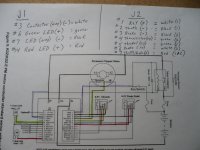
The signal wires connect using (2) aircraft style connectors (J1 & J2)

On the J1 connector, it looks like, we need to connect
...#3 Main contactor driver (-)
...#6 Green LED (indicator) (+)
...#7 LED return (-)
...#14 Red LED (indicator) (+)
* the other connections are optional/if needed
&
On the J2 connector, it looks like, we need to connect
...#1 Key switch (+)
...#2 Throttle (-)
...#3 Brake (-)
...#4 Thermistor (sig)
...#5 Throttle (sig)
...#6 Brake (sig)
...#7 Throttle & Brake (+)
SAM_4433.JPG
 

Functional Artist

Well-known member
Messages
5,350
Reaction score
2,836
Location
Toledo, Ohio
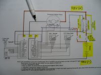
So, let's take a look at the wiring diagram :thumbsup:

* Ima gonna use some 22-4 wire (which is 4 separate, 22g. wires (red, black, green & white) all with-in a common cover

We'll start with the J1 connector.
It only has (4) wires that need to be connected
So I'll use,
...the white wire to connect the #3 pin to the contactor coils (-)
...the green wire to connect pin #6 to a green LED light's (+) (up on the dash board)
...the black wire to connect pin #7 to both green & red LED's (-)
...& the red wire to connect pin #14 to a red LED light's (+) (also, up on the dashboard)

The J2 connector is a bit more complicated.
...'cause, it has (7) connections that are necessary/useful

So, we'll need to use (2) separate pieces of the 22-4 wire
...& to simplify, Ima gonna label 'em (1) "throttle" & (2) "brake"

For the J2 (1) Throttle "cable"
I used
...the white wire to connect the #1 pin to the key switch
...the green wire to connect pin #5 to the throttles signal wire
...the black wire to connect pin #2 to the throttles (-)
...the red wire to connect pin #7 to the throttles (+) *(this supplies 5V to power the throttle)
&
for the J2 (2) Brake "cable"
...the white wire to connect pin #6 to the brakes signal wire
...the green to connect pin # 4 to the thermistor's signal wire
...the black to connect pin #3 to the brakes (-)
...the red wire to connect pin #7 to the brakes (+) *(this also, supplies 5V to power the brake switch)

* Notice the (2) LED's, throttle & brake switches are all (3) wire units
...so, I used the 4th wire in each cable for the "odd" wires (contactor (-), key switch & thermistor)

** I also, used some "color" to highlight where these connections begin, at the controller
...& where they terminate, at their respective components ;)

SAM_4430.JPG
 

Functional Artist

Well-known member
Messages
5,350
Reaction score
2,836
Location
Toledo, Ohio
Did I lose ya yet?
Aw...come on now, we're having fun, right? ;)

It's not that complicated, really :thumbsup:
...& Ima tryin' ta simplify the set-up
...& explain everything as much as I can :cheers2: (in excruciating detail) :innocent::devil2:

* Oh yea, FedEx brought my controller, this eve :bannana:
(all the way from China in (4) days, not bad) :2guns:
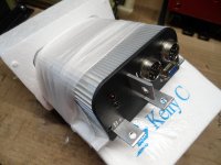
SAM_4412.JPG
 

Functional Artist

Well-known member
Messages
5,350
Reaction score
2,836
Location
Toledo, Ohio
Ok now, let's go back to the diagram
...& take a look at where that resistor & diode go :thumbsup:

The pre-charge resistor "goes" across (connecting) the main contacts, on the contactor
(this allows's a small amount of current to go "cross" the main terminals, which pre-charges the capacitator's in the controller)
...so, that the capacitators don't get "over loaded" by a huge inrush of current, when the contactor "connects" the main contacts.

The diode "goes" across the contactors, coil terminals (the coil is a small electric switch, within the contactor, that when activated, turns on/connects the main contacts)
...this diode, is supposed to block any "feedback" current, that may occur, when the contactor is turned off

I positioned them (resistor & diode) on the diagram, next to where they go
...& also, used a highlighter to "highlight" 'em :cheers2:
SAM_4435.JPG
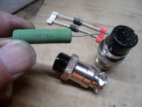
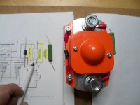
Below is a pic of the contactor, with the pre-charge resistor & diode installed
...& ima pointin' ta where it goes
* This contactor has a 400A rating (to match the controllers 400A rating) & a 48V coil (for use with a 48V system/batt pack)
SAM_4436.JPG
Remember, the J1 connector is just for connecting the (2) indicator LED's & the negative (-) for the contactor's coil

It's the J2 connector, where most of the "action" happens ;)

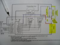
So, we'll start with the J2 connector's, pin #1 labeled PWR.

This where the key switch connects pack voltage (~48V in this case) to the contactors coil positive (+) & to "turn on" the speed controller
...so, that when the key switch is activated, it supplies 48V (+) to the contactor's (coil) & also, to the controller (white wire)

Then, pin #3 labeled Main RLY on the J1, connector supplies the negative (-) to the contactor's coil (black wire)

* Notice, once the key switch is "activated" the contactor has a constant power supply, from the batt pack (orange wire, designating "high voltage (from batt pack to the switch) thru the white wires (that connect the positive (+) from the switch to the contactor & speed controller)
...so, the negative (-) side (black wire) is how the contactor "cuts" the power, to the controller (like if you reach the undervoltage setting etc.)
SAM_4441.JPG
Also, in this pic, I highlighted the battery pack, circuit breaker (resettable "main" fuse) :cheers2:
...& a fuse (5A) (this protects the controller & the contactor's "signal power" circuits)
 
Last edited:

Functional Artist

Well-known member
Messages
5,350
Reaction score
2,836
Location
Toledo, Ohio
Battery Cables

Ok so, we know how the contactor, needs to be connected
...the smaller "coil" terminals are for connecting the small coil wires (~22g.)
...& the big, "main" terminals are for connecting the big battery cables (~4g.)

So, let's go over where the battery cables connect :thumbsup:

The positive (+) battery cable starts at the battery pack's positive (+) terminal
...& connects to the "in" side of the contactor's "main" terminal

Then, another cable goes from the "out" side of the contactor's "main" terminal
...to the motor's positive (+) terminal (A2)
...& also, to the controller's positive (+) terminal (B+)
SAM_4443.JPG
The negative (-) battery cable starts at the battery pack's negative (-) terminal
...& connects to the controllers negative (-) terminal (B-)
SAM_4444.JPG
Then, we also, have another negative (-) cable that starts at the controller's (M-) terminal
...& connects to the motor's negative (-) terminal (A1)
SAM_4445.JPG
 

Functional Artist

Well-known member
Messages
5,350
Reaction score
2,836
Location
Toledo, Ohio
Now, all we have left to connect are the signal wires (LED's, throttle, brake & thermistor)

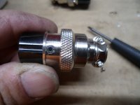
So, let's look at the J1 & J2 connectors.
(there's a small screw on the side that need to be removed & then ya just give 'em a twist & slide 'er apart)
SAM_4415.JPG
Here are the little "pins" where the wires connect
The pins are labeled/numbered on the front side (ta help ya know which is which)
SAM_4417.JPG
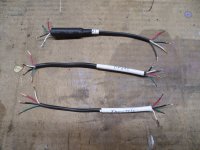
So, I made up a couple of short (~6") harnesses & labeled them (J1, J2 Throttle & J2 Brake)
Since J1 only has 1 harness going into it, I wrapped a piece of Gorilla Tape (HD Duct Tape) around it ta "beef" 'er up a bit
...& then, some shrink wrap.
On the other (2) I used some of the Gorilla Tape just to label 'em
SAM_4419.JPG
I "tinned" (added some solder to the ends of) the wires & the "pins" too
...then, started attaching the wires to their designated positions
Here is the J1 plug with its (4) wires soldered "in place"
SAM_4426.JPG
Here are both the J1 & J2 connectors all ready to connect
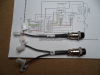
I also, added some plug ends, to easily connect with the existing plugs on the throttle & such
SAM_4428.JPG
 

Attachments

  • SAM_4418.JPG
    SAM_4418.JPG
    3 MB · Views: 0
Top