Grand Daddyish build

TNThomas

Well-known member
Messages
495
Reaction score
595
Location
Washington
Those rear springs and shocks, you’re not going to leave them like that are you? They will be in a bind that way. Not good. Just something to think about.
Not 100% sure what you are refrencing. Ive done a light load test, and springs conpressed just fine. Its also hard to see on thd pics, but my atrachment methos to the frame sown low doesnt allow for much side to sise mocement. If I do have issues, ill make a panhatd bar setup to help.
 

TNThomas

Well-known member
Messages
495
Reaction score
595
Location
Washington
Coil overs need to be angled in the direction of the arc the rear will travel in.
Ah, I see, thanks for the input! They are angled in the direction of the arc, but not as much as most builds, its hard to see the offset from the last pic. I did this because I have the exact opposite problem as alot of karts, the shocks /struts are actually meant for a small truck, so they are fairly stiff. To maximize the force actually compressing the shock, I kept the angle fairly shallow, that way the force vector is almost in line with the shock. Worst case scenario I can just weld on another atrachment point to tweak the angle. I have a secobd set of shocks as well in case my load estimation is totally wrong. I got the 2/4 rear axle bearing ls on last night, pics to come.
 

TNThomas

Well-known member
Messages
495
Reaction score
595
Location
Washington
I double checked to be safe, and I should be alright. My rear shocks have about 9-ish" of travel, and at max compression they would still be slightly angled forward, and near vertical. The last few inches of travel should result in stiffer shocks, both fron the compression, and from the the force vector no longer being in line with the shock (less force in the shock direction). But I doubt ill go too far beyond halfway compressed. First pic shows 10.5" of travel, 1.5" bey9nd what mine can compress. Worst case ill just add new mounts, I have 4 extra, but I think im good.

I am planning on putting a second set of bearings essentially within 1/2" of the hub, almost inside the wheel. Ill weld square tube and angle itin on the outside of the current bearing bracket, in a specific orientation as to keep the bolt hokes accessable. Should eliminate bent axle worries.
 

Attachments

  • 20221230_002838.jpg
    20221230_002838.jpg
    1.8 MB · Views: 22
  • 20221230_004312.jpg
    20221230_004312.jpg
    1.8 MB · Views: 21
  • 20221230_010158.jpg
    20221230_010158.jpg
    2.9 MB · Views: 18
  • 20221230_005821.jpg
    20221230_005821.jpg
    4 MB · Views: 19
  • 20221211_203309.jpg
    20221211_203309.jpg
    3.5 MB · Views: 25
Last edited:

TNThomas

Well-known member
Messages
495
Reaction score
595
Location
Washington
That will work! Just straight up and down is a bad idea! Carry on and forgive my interruptions!
No worries, I appreciate the brain power! Ill probably weld 1 more top attachment on, lower down to provide a second attachment point to angle it a forwatd if needed. Easy to do now.
 

madprofessor

"Loose Cannon Creations"
Messages
2,899
Reaction score
960
Location
Jacksonville, Florida
Coil overs need to be angled in the direction of the arc the rear will travel in.
Sounds like the angles being discussed aren't sharp enough to affect what I'm thinking about, but want to chime in anyway.............
We're all familiar with increasing possible wheel travel by slanting an overly stiff coilover away from the vertical for a greater ratio between wheel travel and shock travel. I personally am not lucky enough to order shocks out of a catalog that are the perfect amount of stiffness (or easily adjustable to it) for vertical compression first time out. Making them work via angled compression over straight compression is a good answer as opposed to reordering different shocks.
The thought I wanted to put forward is about when that steeper angle is used, that there's 2 ways to go about it. (Thinking of my cantilevered coilovers brought the thought.) If the shocks are angle-mounted so that the further the wheel travels up, the more vertically the shocks compress in the arc of travel, that's the increasing resistance of any coilover being compressed.
The opposite does the opposite. If the arc of travel angles the shocks further away as the wheel travels up, then you get diminishing resistance as the wheel travel increases. Creates a completely different ride for offroad, and I'd say changes handling to a degree also. My weird setup is a very extreme example, but was meant to be, to be one of a kind.
 

Attachments

  • 100_0170.JPG
    100_0170.JPG
    2.3 MB · Views: 8

TNThomas

Well-known member
Messages
495
Reaction score
595
Location
Washington
Sounds like the angles being discussed aren't sharp enough to affect what I'm thinking about, but want to chime in anyway.............
We're all familiar with increasing possible wheel travel by slanting an overly stiff coilover away from the vertical for a greater ratio between wheel travel and shock travel. I personally am not lucky enough to order shocks out of a catalog that are the perfect amount of stiffness (or easily adjustable to it) for vertical compression first time out. Making them work via angled compression over straight compression is a good answer as opposed to reordering different shocks.
The thought I wanted to put forward is about when that steeper angle is used, that there's 2 ways to go about it. (Thinking of my cantilevered coilovers brought the thought.) If the shocks are angle-mounted so that the further the wheel travels up, the more vertically the shocks compress in the arc of travel, that's the increasing resistance of any coilover being compressed.
The opposite does the opposite. If the arc of travel angles the shocks further away as the wheel travels up, then you get diminishing resistance as the wheel travel increases. Creates a completely different ride for offroad, and I'd say changes handling to a degree also. My weird setup is a very extreme example, but was meant to be, to be one of a kind.
Thats very well worded, and makes sense. This would be a fantastic entry level college physics question for students. Your built suspension setup is pretty cool, basically redirecting force in multiple directions. With your setup you could also theoretically adjust bolt rotation points to increase/reduce torque acting on the shock, a potential third way of adjusting "stiffness".

Your comment on the diminishing resistance basically what inspired me to have a shallow angle. Stiff shock, so I need the most force possible being applied to it as its compressed (rotates toward near vertical at max compression). But, I realized after Denny's comment that it actually should be angled a touch more extreme/forward to accomidate my logic. Not much, maybe 5-10 deg or so.

On a side note, im a HS teacher, and students often complain about never needing math/sci in the real world. I got tired of it a few years ago so I brought my dirtbike into the classroom and had students work in pairs to dismount and remount my tires and chain, along with adjusting chain tenstion. Kids loved it! Teachers looked at me a little weird pushing a motorcycle down the hallway though!

Shop manual, torque specs, wrenches, torque specs, etc. Its a little spooky with the amount of kids in the urban environment who have never touched basic tools.
 
Last edited:

madprofessor

"Loose Cannon Creations"
Messages
2,899
Reaction score
960
Location
Jacksonville, Florida
Its a little spooky with the amount of kids in the urban environment who have never touched basic tools.
Agreed! Have seen way too much of it through my son's spoiled friends to believe there's been a whole lot of hands-on Daddy teaching at home about the physical world and how to live well in it.
theoretically adjust bolt rotation points to increase/reduce torque acting on the shock
Absolutely correct, Teacher. A close look at my setup however, might reveal how I made the joints, and why it was weld, cut, reweld to get the desired action instead of having varied and easily adjusted mounting points. To be even more unique in that build, I didn't make hinge points. The pivots in the suspension (and in the steering linkage) are made of 3/4" threaded rod screwed through 3/4" threaded rod couplings, and literally screw in/out as they pivot. Much more engineering involved, especially in the steering. Had to put an extra hexagonal quick-release hub in the steering linkage for free motion in/out to stop binding as the wheel kept turning. With the dual-position steering wheel, it now has 4 completely separate quick-releases......... 1 for the wheel itself, 2 for the moveable left or center shaft, and 1 for the floater out front.
 

Attachments

  • IMG_20210718_164713.jpg
    IMG_20210718_164713.jpg
    2.5 MB · Views: 10
  • IMG_20210718_164745.jpg
    IMG_20210718_164745.jpg
    2.5 MB · Views: 10

TNThomas

Well-known member
Messages
495
Reaction score
595
Location
Washington
In the quest to not bend my itty-bitty 1" dia axle, I mounted 2 bearing holders, and positioned the bearings on the outside, in such a way that I was able to essentially "box out" steel supports to hold the outer bearing within 1/4" of the Hub. I'll do full welds after I take the bearings off as not to melt the rubber. This way, even with a flat, I shouldn't experience any rubbing of the tires, and minimal torque from the axle wanting to bend. The bearings need to be mounted in a specific orientation, with Angle Iron used on one side to allow access to the bolts. Images show the swingarm in the upside-down position.

I am not terribly impressed by these stock hubs (the weld don't look great, look surface welds with minimal penetration), so I will weld on four little gussets for each side to help stabilize.
 

Attachments

  • 20230111_170226.jpg
    20230111_170226.jpg
    3.2 MB · Views: 12
  • 20230111_170218.jpg
    20230111_170218.jpg
    3.4 MB · Views: 12
Last edited:

TNThomas

Well-known member
Messages
495
Reaction score
595
Location
Washington
Tacked up. Full welda next.
 

Attachments

  • 20230112_222045.jpg
    20230112_222045.jpg
    2 MB · Views: 18
  • 20230112_232148.jpg
    20230112_232148.jpg
    4.1 MB · Views: 17
  • 20230112_232140.jpg
    20230112_232140.jpg
    2.8 MB · Views: 17

TNThomas

Well-known member
Messages
495
Reaction score
595
Location
Washington
Status update:

I havn't done much on the buggy for the last 2 weeks, I'll start working on the swingarm today and later this weekend. I built 2 walls in my garage to make a private entrance, and made 2 storage racks, hence the slow moving on the buggy recently. Lots of target shooting and reloading too. Baby #3 is due in May, so I want to finish the buggy before then.

Next up is to weld the supports and engine mount plate onto the swing arm, then i'll beef up the swingarm with gussets, then get the tie rods made (since I know where the axle sits I can do a proper ackerman steering). Then I'll get the engine mounted up, sprockets, chains, brakes, etc. Once most of the wait is on the vehicle, I'll do a rear spring compression test to see if I need more support in the back. If not, I'll proceed to get some sort of paint on everything, then finish out all the connections/gas tank/pedals, all that stuff.
 

Attachments

  • 20230102_192410.jpg
    20230102_192410.jpg
    1 MB · Views: 3
Last edited:

TNThomas

Well-known member
Messages
495
Reaction score
595
Location
Washington
-1/4" of axle between outter bearing and hub
-Extra bearings directly under rear shock
-Engine plate is next
-Then gussets
 

Attachments

  • 20230204_013807.jpg
    20230204_013807.jpg
    3.9 MB · Views: 22
  • 20230204_013924.jpg
    20230204_013924.jpg
    3.9 MB · Views: 21
  • 20230204_013853.jpg
    20230204_013853.jpg
    3.4 MB · Views: 20

TNThomas

Well-known member
Messages
495
Reaction score
595
Location
Washington
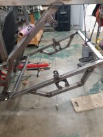
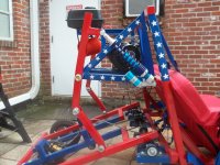
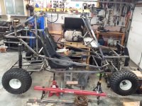
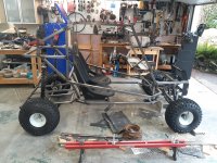
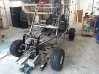
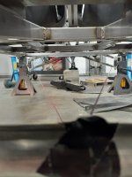
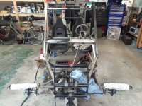
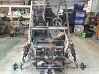
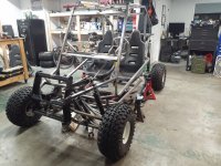
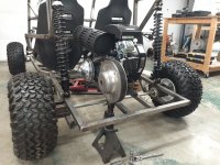
Ok, finally got the buggy off of jack stands, with all of the current weight on the tires/shocks:

1) The "dune buggy" now feels much more like a big go-kart now that its almost a foot closer to the ground.
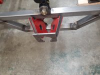
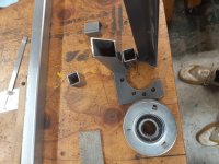
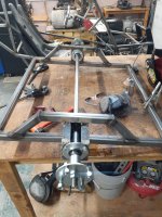
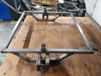
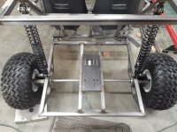
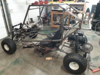
2) I tacked on the engine mounting plate. Im about 95% positive of its location, but no harm done waiting for full welds.
3) Im closer to being done than I thought, thibgs like breaks/throttle are not far out.
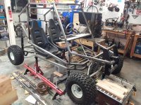
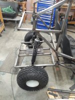
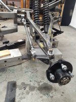
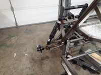
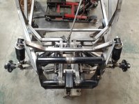
4) I got lucky and guessed spot on with the rear shocks. They are stiff, but not too stiff, and tgey have about 10" of travel. I doubt ill need it, but its there.
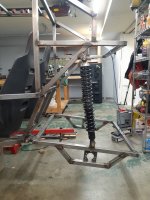
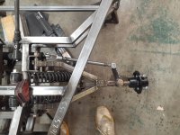
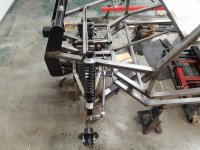
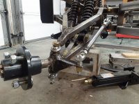
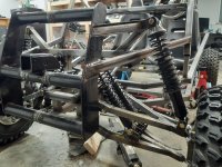
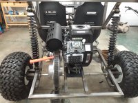
5) Front shocks, I didnt guess as well. They are WAY too steep of an angle, and under full load the A-arms are basically parralel with the ground. In hindsight I think they would be fine if they were more upright, but im in too deep to easily change that.
6) To fix the front, ill start easy and put a third shock at a much more vertical angle, ill mount it on the top A arm, and the vertical bolt will be on the outside of the support bar running from my bumper to roll cage. The lower mount will be within an inch of tge outtee end of tge top A-arm. That will help reduce the torque from the eztra length if A arm between the tire and wheel. The 2 current shocks definitely have that as another issue causing them to collapse easily. If that all fails, ill chop all three shocks out, and put the same springs I have in the back, up front. If I could go back in time, thats exactly what I would do. They wouls be a little stiff, but good enough.
6) While Im waiting for parts ill make my tie rods

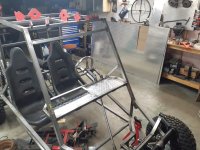
The pic with the wheels on the ground has a jack under the front to stop it from collapsing.
 

Attachments

  • 20230205_110414.jpg
    20230205_110414.jpg
    3.8 MB · Views: 22
  • 20230205_110359.jpg
    20230205_110359.jpg
    3.4 MB · Views: 21
  • 20230206_125213.jpg
    20230206_125213.jpg
    4 MB · Views: 18
  • 20230206_125303.jpg
    20230206_125303.jpg
    1.8 MB · Views: 20

TNThomas

Well-known member
Messages
495
Reaction score
595
Location
Washington
Pretty happy with how it turned out. I read somewhere to make one end of the tie rod reverse threads (lefty-tighty), sure makes adjusting the tie rods easy with those. The lower welded nut on the tie rod is LH, the upper welded bolt is RH threads.

Couple extra pics with the new shocks to stiffen the A-arms up. They will be mounted early exactly as shown, one on each side. If its too still ill take off one of the smaller shocks.
 

Attachments

  • 20230215_190627.jpg
    20230215_190627.jpg
    4.2 MB · Views: 23
  • 20230215_190651.jpg
    20230215_190651.jpg
    1.7 MB · Views: 20
  • 20230215_190743.jpg
    20230215_190743.jpg
    3.1 MB · Views: 18
  • 20230215_190746.jpg
    20230215_190746.jpg
    3.9 MB · Views: 21
  • 20230215_203606.jpg
    20230215_203606.jpg
    3.1 MB · Views: 22

TNThomas

Well-known member
Messages
495
Reaction score
595
Location
Washington
Lots of progress in the last 24 hours. The third set of shocks fixed and ride height is now good. I used spindle mounts and cut them down for the shock mounts.
 

Attachments

  • 20230304_123426.jpg
    20230304_123426.jpg
    3.1 MB · Views: 20
  • 20230304_123705.jpg
    20230304_123705.jpg
    3.5 MB · Views: 15
  • 20230304_201040.jpg
    20230304_201040.jpg
    3.2 MB · Views: 16
  • 20230304_195739.jpg
    20230304_195739.jpg
    4 MB · Views: 16
  • 20230304_201051.jpg
    20230304_201051.jpg
    2.8 MB · Views: 19
  • 20230304_201028.jpg
    20230304_201028.jpg
    3.3 MB · Views: 19

TNThomas

Well-known member
Messages
495
Reaction score
595
Location
Washington
Mocked up the 670 and cvt so I can plan out jackshaft spacing

Spent today in the rain digging a french drain. Im really impressed with this Honda GX160 engine on this tiller, its a little monsterz abd always works, super simple.
 

Attachments

  • 20230311_215813.jpg
    20230311_215813.jpg
    3.5 MB · Views: 19
  • 20230311_215823.jpg
    20230311_215823.jpg
    3.2 MB · Views: 19
  • 20230311_215837.jpg
    20230311_215837.jpg
    3.3 MB · Views: 17
  • 20230311_220640.jpg
    20230311_220640.jpg
    3.4 MB · Views: 17
  • 20230312_172422.jpg
    20230312_172422.jpg
    2.7 MB · Views: 19

TNThomas

Well-known member
Messages
495
Reaction score
595
Location
Washington
Lots of parts coming in. Im going with a 1" jackshaft due to the Snowmobile driven CVT size (1"). I ordered sprockets last night. I was having a hard time finding what I wanted from GPS or BMI, so I bought my sprockets/chain from "Nitro Chains." Way larger selection than the chinese made stuff. I also bumped up the chain/sprocket size to #50 chain just to be consistent on keeping everything strong. I went with a 65 tooth driven/final sprocket, and 10, 12, and 14 tooth drive sprockets from the jackshaft. That way I can make a few spare chains to mess around with gear ratios.
 

TNThomas

Well-known member
Messages
495
Reaction score
595
Location
Washington
Got the jackshaft and seat belts in the mail today. Seeing the finish line baby! Little by little. I found a killer deal on a bunch of diamond plate from a drill rig. Planning on doing the floor, mini bed in the rear, potentially the roof, and a few other areas with this.

Im getting closer to a chosen color for the paint. One of my co-workers knows his stuff for painting as he makes custom electric guitars. He turned me on to "metal-flake," and I think im going to just go all out with sparkle/shiny. Essentially a dark purple/black multi color sparkle for the frame. Gas tank will likelt be reflective silver with multi color "big" flake sparkles. Going for this on the frame unless I change my mind:


Attachments

  • 20230322_203801.jpg
    20230322_203801.jpg
    3.4 MB · Views: 3
Top