Diamonite Electrathon America Racer

Functional Artist

Well-known member
Messages
5,497
Reaction score
3,075
Location
Toledo, Ohio
How's ducky?

What a suprise homecoming.
How long was the power out?
Hey WTR,

Ducky don't like storms (or fireworks)
...& just hides under the neighbor's motorhome
...until the "coast is clear"

No power for (2) days
...& yup, it was still in the 90's :surrender:

So, on Friday, I still got some stuff done (American ingenuity)
...just had ta do "powerless stuff"

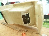
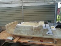
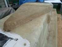
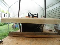
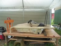
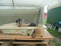
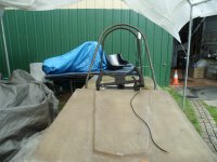
Like, cleanin'/wipin' the monocoque down
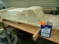
SAM_8186 (1).JPG
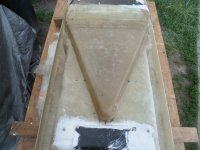
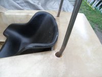
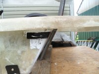
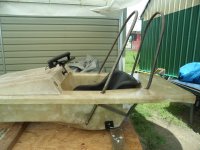
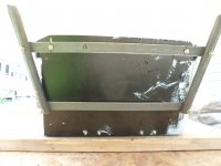
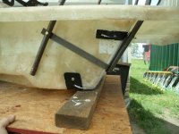
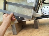
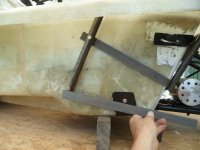
Ez suggested bondin' the steel "saddles" to the FG monocoque :cheers2:
&
I had ~1/4 of a can of the Appliance Epoxy brush-on paint
...& Epoxy "is glue"
&/so
I gave all of the mounting surfaces a good coatin' of "the glue"
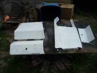
SAM_8188 (1).JPG
...& on the "saddle" area of the monocoque too
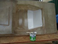
SAM_8187 (1).JPG
Installed 'em while still "tacky"
...w/nuts & bolts
...to "lock 'em in place" :2guns:

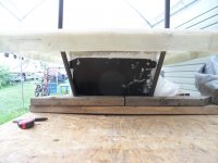
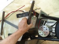
Here is an inside view (after installation)
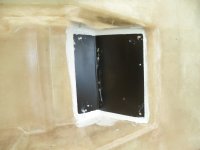
SAM_8191 (1).JPG
Underside
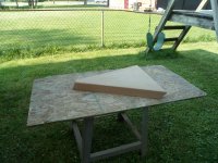
SAM_8189 (1).JPG
 

Functional Artist

Well-known member
Messages
5,497
Reaction score
3,075
Location
Toledo, Ohio
That’s what you get for painting everything Satian Black. :ROFLMAO:
Hey Denny,

Satian has nothin' ta do with it :confused:

Satan Black paint is just my "go to" for misc parts :thumbsup:

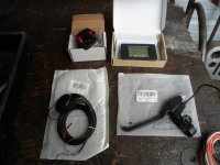
Now, let's look at some of the electronical parts
SAM_8193 (1).JPG
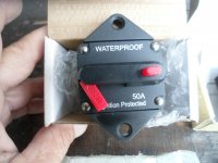
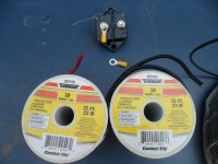
48V 50A Circuit Breaker
Because this racer will operate on a 48V battery pack/system
...& the Speed Controller has an Amp rating of ~30A (nominal)
...with potentially a peak Amperage of ~40A
...&/so, a 50A breaker should be appropriate :thumbsup:
&
This component will "serve" as both a resettable fuse
...& a manual "main" power cut-off switch too :cheers2:
SAM_8194 (1).JPG
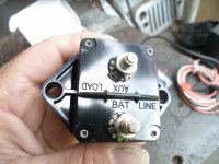
Here is the backside (power connections)
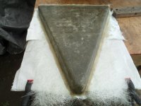
...& it MUST be "wired" appropriately
...to function properly :geek:

* The positive (+) cable, from the battery, connects to the "BAT LINE" terminal
...& then, another (+) cable goes from the "AUX LOAD" to the Speed Controller
SAM_8195 (1).JPG
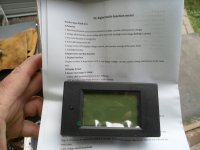
This is the PZEM-051 Power meter (more on this little "guy"...later) ;)
SAM_8196 (1).JPG
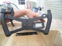
* Also, shown (in the first pic) is the Thumb Throttle
...& a hand brake lever (with a brake light switch)
 

Functional Artist

Well-known member
Messages
5,497
Reaction score
3,075
Location
Toledo, Ohio
Workin' on "dash "lay-out" ideas (doesn't require any power)

* The EA rules stipulate:

12 ELECTRICAL SYSTEM
1. A fuse or circuit breaker is required in any electrical circuit between the battery and any electrical device.
2. All fuses or circuit breakers should be mounted as close as practically possible to the source of power.
3. All fuses or breakers should be sized to protect the wiring to which they are connected.
The current rating of fuses and breakers shall be no more than those listed in the adjacent table for standard automotive cable.
&
13 ISOLATION SWITCH
1. An isolation switch (kill switch) is required on all vehicles. This switch must have a break current rating that exceeds the maximum current draw of the vehicle.
2. The switch must be located in the main positive power cable between the battery and any motor controller.
3. An actuator may be attached to the switch for remote operation provided that it is durable and reliable.
4. Means must be provided for both the driver and race officials to actuate an isolation switch.
5. The driver must be able to actuate the switch while in driving position and without reaching outside the vehicle.
6. Race officials must be able to actuate the switch from outside the vehicle without reaching in.
7. Two switches may be installed if necessary.
8. A circuit breaker may be used as the isolation switch.
9. The switch or actuator accessible from outside the vehicle must be mounted within a solid red triangle whose sides are at least 4 inches and in contrast to vehicle color or graphics.
10. Wiring must be well insulated and securely attached to the frame or body. All wiring must be kept free from moving parts and protected from chafing.
11. Wiring that passes through a hole with sharp edges or through sheet metal must be protected by an insulating grommet or other suitable device.
12. Terminals must be secured so they will not come loose or short out during a competition.
13. No part of the electrical system may use the vehicle frame as a conductor. The frame must not be grounded.
(page 9.)

Let's concentrate on these:
1. An isolation switch (kill switch) is required on all vehicles.
2. The switch must be located in the main positive power cable between the battery and any motor controller.
3. An actuator may be attached to the switch for remote operation provided that it is durable and reliable.
4. Means must be provided for both the driver and race officials to actuate an isolation switch.
5. The driver must be able to actuate the switch while in driving position and without reaching outside the vehicle.
6. Race officials must be able to actuate the switch from outside the vehicle without reaching in.
7. Two switches may be installed if necessary.
8. A circuit breaker may be used as the isolation switch.

So, maybe...
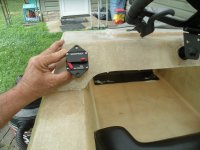
As the driver can easily reach it "without reaching outside the vehicle"
...& race officials can easily reach it "from outside the vehicle without reaching in"

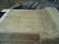
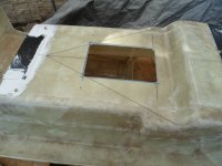
SAM_8200 (1).JPG
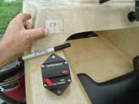
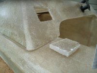
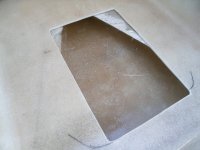
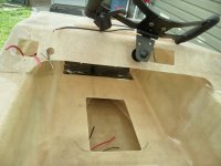
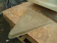
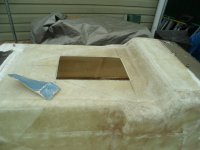
I used a template to mark the required opening
SAM_8202 (1).JPG
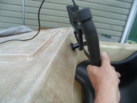
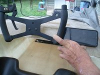
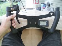
Here's what I'ma thinkin' for the hand brake lever
...but, NOT the power meter
...as the brake lever & the drivers hand would be blockin' the view of it
SAM_8208 (1).JPG
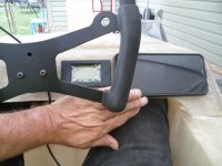
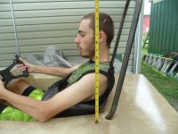
Side view showing "dash to steering wheel clearance"
SAM_8206 (1).JPG
Looks like the power meter should be easily seen...on the other side...about here
SAM_8209 (1).JPG
...& the Speed-o-meter (phone w/app) should be easily seen...about here
SAM_8210 (1).JPG
 
Top