Budget stock 212 Hemi TORQUE MONSTER build!

Messages
143
Reaction score
6
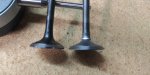
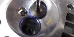
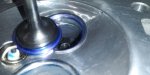
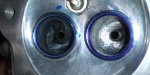
Numbers are in. These are the 28"H2O numbers of depression for both intake and exhaust. I will swap my set-up to blow through from combustion chamber side out the exhaust later for proper exhaust numbers later. The intake flows 16.40cfm @ .100" lift and 22.46cfm @ .261" lift at 10"H20 for those of you who appreciate the 10"h2o at .100" and max valve lift numbers. I need to tighten up the exhaust port some but I knew that before I flowed the head. I am working on the proper exit angle and position but will be tightening it up soon. You can see that the intake port levels out at about 36cfm between .175" to max lift at .261". The port velocity will ramp up if the piston speed increases so the velocity will be higher even though the max cfm maxes out at 36cfm but it will be at a point where the piston is slowing down so there should not get close to sonic choke.
Note: I made a Helgesen calibration plate and calibrated using the 20cfm and 30cfm holes. My setting is based off from flowing 27.25cfm on the 30cfm and 18.80 on the 20cfm just to give some room for error so that I wasn't too far over since my numbers seemed high.

INTAKE @ -28"H2O:

Valve Lift CFM
.012 6.35
.025 9.45
.050 15.10
.075 19.00
.100 26.45
.125 31.60
.150 34.25
.175 35.90
.200 36.15
.225 36.50
.250 36.80
.261 36.80

EXHAUST @ -28"H2O:

Valve Lift CFM
.050 13.80
.075 19.00
.100 23.55
.125 27.00
.150 29.30
.175 31.25
.200 31.80
.225 33.10
.250 34.50
.264 35.10
 
Last edited:
Messages
143
Reaction score
6
So if you calculate how much CFM is required to fill the cylinder 100% with air you take the displacement and multiply by the max rpms and then divide by 3456. So the bore is 2.756" and the stroke is 2.165". Take the area of the bore and multiply it by the stroke to get the total displacement of 12.9153"^3. Let's round that up to 12.93" just to be sure we get enough for extra tolerance that may occur. Aim high on our max rpm at 6,000 just to be sure.

(12.93×6,000)÷3456=22.45cfm needed on average per intake stroke for 100% cylinder fill when turning 6,000rpm.

The intake port supports 22.46cfm at only 10inH2O at max lift of .261" and 22.45cfm probably around .80"-.90" @ 28inH2O.

So I feel that I am in the ballpark of where I need to be if there are excessive pumping losses or if the intake runner becomes too restrictive due to length. But if the pumping losses are minimal and tge intake doesn't add much restriction then I could probably tighten the port up just a tad more and pick up a bit more velocity. As for the exhaust it only needs to flow about 70% or so of the intake so I will be adjusting it down some while I adjust the exit angle and exit position to be sure that I keep the exhaust velocity where it needs to be to properly scavenge the head.

When you consider that the minimum cross-sectional area of the ports are less than half that of the stock ports you can see that the improvement in angle of approach to the valve seat and gradual short turn radius eliminated much of the turbulence since the flow numbers did not drop much from the stock numbers that are posted by others online. So I hace picked up a considerable amount of velocity but am still able to flow enough total cfm needed to fill the cylinder at 6,000rpms (in theory). Stock flow numbers range from 45-52cfm max lift @28inH2O. Normal heads flow about 43-45cfm, high flowing heads might flow about 50-54cfm.

Flow needs considering losses:
22.45cfm @ 30% losses= 29.185cfm
22.45cfm @ 45% losses= 32.55cfm
22.45cfm @ 60% losses= 35.92cfm

I think I will work the intake port a bit to see if I can pick up some flow at low lift and work the seats and put it on the engine under load to see if it runs out of air and to see how well it runs all around and go from there. I might be wrong so that is a sure fire way to test and see. I will tighten up the exhaust a bit and work the seats as well before I put it back together.

What do you guys think? Think it will run great, just ok or be a turd??
 
Last edited:
Messages
143
Reaction score
6
Pressurized (blow thru) Numbers:

INTAKE
Tested @ 28inH2O
Lift CFM
.025 Did not register
.050 7.266
.075 16.43
.100 19.35
.125 22.45
.150 24.50
.175 25.34
.200 26.23
.225 26.57
.250 " "
.261 " "

EXHAUST
CFM CFM @
Lift @ 28" Max Pressure
.025 Did not register (could feel wind coming out of port though)
.050 8.89 10.65
.075 13.92 17.43
.100 17.85 20.58
.125 20.50 23.11
.150 23.24 25.73
.175 25.10 28.00
.200 26.38 29.57
.225 28.20 30.65
.250 29.07 31.27
.263 29.30 31.72

After 3-Angle valve seat and altering the valve
EXHAUST

.025 3.32 4.83
.050 8.96 10.87
.075 14.24 17.00
.100 18.40 20.55
.125 21.26 23.55
.150 24.07 26.29
.175 26.23 28.41
.200 27.89 30.08
.225 28.76 31.10
.250 29.84 31.74
.263 29.84 31.80

INTAKE
Tested @ 28inH2O

Lift CFM
.025 6.48
.050 11.44
.075 19.05
.100 22.56
.125 24.50

Intake is just for data and to check reversion/Anti-reversion numbers.

Depression numbers for intake after 3-Angle Seat and valve back-cut later.
 
Last edited:
Messages
143
Reaction score
6
A few pics of the valve seat cutting, lapping and before and after of how the valves sit in the seat. Since this thread is dead I did not take the time to take more pics or elaborate on details of the process.
 

Attachments

  • 20200906_161708.jpg
    20200906_161708.jpg
    2.2 MB · Views: 4
  • 20200906_074009_HDR.jpg
    20200906_074009_HDR.jpg
    1.7 MB · Views: 5
  • 20200906_141418.jpg
    20200906_141418.jpg
    2.8 MB · Views: 4
  • 20200906_125153.jpg
    20200906_125153.jpg
    2.6 MB · Views: 4
  • 20200906_112316.jpg
    20200906_112316.jpg
    2.8 MB · Views: 5
  • 20200906_085131.jpg
    20200906_085131.jpg
    3.7 MB · Views: 5
Messages
143
Reaction score
6
A few details in case any future viewers want to know...

I back-cut the intake valve only. With the stock cam I don't think there is enough lift/stroke timing to worry about the additional reversion flow during the start of the compression stroke and I think the compromise for the additional gain of flow during overlap is worth it.

I radiused the exhaust valve some for improved flow but left plenty of shoulder to prevent the valve from burning. I did a 3-angle cut on the exhaust valve seat to place the seat properly and widened the contact patch to about .004". Stock the contact patch was about .001" or less and the valve rode very high on the seat which left the valve overhang about .004" above the seat face and there was about a .0065" shoulder. The compromise between a thinner or wider seat patch is with a thin contach patch the spring pressure is distributed only over a thin area which can provide a more stout pressure, however if it is too thin it can create sealing issues, especially at high rpms. Also, the contact patch acts as a heatsink to help dissipate heat from the valve. A smaller contact area won't dissipate as much heat or as fast as a wider seat-to-valve contact patch. So I elected to widen the contact patch and settled the valve further down into the pocket for better sealing, better heat dissipation and overall reliability.

I also did a 3-angle cut on the intake seat. I was a little more aggressive with the 60 and 30 angles in an attempt to create crisp angles to sheer fuel some and improve low-lift flow. The 45 is about .003" wide, .004" from the top of the lip and about .002" from the 28° to 23° radiused back-cut that has a slightly roughed surface.
 

Attachments

  • 2020-09-06 17.22.11.jpg
    2020-09-06 17.22.11.jpg
    2.4 MB · Views: 3
  • 2020-09-06 17.24.41.jpg
    2020-09-06 17.24.41.jpg
    3.7 MB · Views: 3
Messages
143
Reaction score
6
Given the exhaust number comparison between before and after the seat and valve work I will have to spend some attention on the seat below the 60° cut to improve low-lift flow. The area below the bottom cut and how it blends with the bowl gives the characteristics as to where the benifits from a 3-angle seat will in the valve lift range. The length and radius below the bottom cut is very important. I will try to get it to flow better at low-lift.
 
Messages
143
Reaction score
6
Ok, I worked the exhaust seat below the bottom cut and seat-to-bowl transition and reflowed it. New #'s.
CFM @ CFM @
Lift 28"H2O MAX
.025 2.91 3.94
.050 9.20 11.29
.075 13.93 16.56
.100 18.70 21.24
.125 21.61 23.51
.150 24.11 26.45
.175 26.21 28.85
.200 27.37 30.35
.225 28.66 31.30
.250 29.39 31.83
.263 29.58 32.19

So I picked up a number at .025" lift which is near where it might be of some use during overlap. There was some gain all the way through the range and still seemed to have small gains up top, which surprised me. I am happy with the alterations I have made. Now on to depression to see what I picked up on the intake.
 

Willisk2004

Williskart
Messages
34
Reaction score
6
Location
Telford TN
For all the work and money spent, just buy a big block! I just put a duromax 440cc on mine with header and valve springs. ( mikuni to come ) got tired of fooling with no start issue. ( I now know how to fix but need time to remove governor! But point is I can pull the wheels with a blip of the throttle with just about stock engine that cost $330 on Amazon. That being said I can appreciate the research and ingenuity that you are putting your mind to! Maybe once I have my shop built next month and get organized I’m sure I’ll find myself in a similar situation !
 
Messages
143
Reaction score
6
Thanks. Yes, if I needed that much more power and wanted to spend the extra $230 I would for sure just buy a big block. This is much more about just testing out theories and ideas I have, and doing it on a cheap engine, than it is about actually making huge power improvements. It's more about time than money, and even more about making improvements and getting the most out of something than needing the extra power. There is great value in learning how to make things perform better andthe satisfaction of accomplishment when done is very special.

The experimental process and learning while doing projects such as this one is hugely valuable to me. Ihave this experience and knowledge forever and can apply them down the road along with all the rest that I have, and will continue to, accumulate. With this knowledge I can quickly duplicate the end goal to other projects which will use this same engine (which there will will be many) and it won't take nearly as much time. Plus I will know better what to adjust for other applications. So when I do get a big block I can tear it down, take measurements and know how to make it better for my exact goals. None of these engines are perfect for all applications. They are a base platform that are designed to so a simple industrial job. We can make changes to fit our needs that will drastically change the characteristics to perform more the way that you want it to. It usually only takes knowledge and time, plus a tiny bit of money for parts and supplies. If you want to go big horsepower and an expensive build then the additional knowledge is even more important! So I am just a humbled fool in search of knowledge and understanding inspired to make things better.
 
Messages
143
Reaction score
6
While I was working on the exhaust valve seat throat area I flipped tge head around in the fixture and continued to radius and angle but I didn't pay attention and was taking material out of the intake. I did this not once, but twice! My intake was already where I wanted it to be. I finished up the exhaust and tested it and got the results that I wanted. I switched over tge flowbench to run depression and etested the intake and found that I had lost about 9cfm on the high lift, 3cfm mid-lift and it's not as responsive at low-lift as I expected.

So I am certain the 2 goof ups are mostely to blame but I cannot rule out the seat or valve work. So I am trying to sort things out. On a brighter note I get to see where I lost the flow by figuring out exactly what I messed up... which is kinda the whole point of all of this in the long run. I might even grab some valve seats and valves and try a 35°-38° seal angle with a large contact width with 45° and 30° top cuts and a 68° bottom cut along with a seat offset and smaller thoat diameter, which I think is more suited for this engine.

Along with the throat area mishaps I also decided to clean up a few spots in the bowl while I was already set up at my porting station. This is another area where I could have lost cfm. Normally I do things one at a time and collect the data for each change so that I know what affected what and how much. Now I have to make changes to try to decipher what exactly screwed things up. So for those of you who don't already know the best way to make changes is to do only one thing at a time and collect data on each and every step so that you know exactly what improves or declines and how much.. Otherwise you end up in the position that I'm in now and can only guess which one or multiple things screwed things up and if something had an improvement but you can't know because the overall end results are of an overall decline. I knew better but I was on a roll and making lots of positive progress and just wanted to hurry up to get things where I wanted them, slap it back together and see what real world results I got.

So I am trying to bring things back to where they were. I redone the bowl and will need to reshape it to how it was, I have new valves on the way and am considering grabbing some seats also. I think I will try the port first. Try the stock valve with bowl. Then try adjusting the seat. And then buy new seats if I have not got back to where I was or better.

I have a nagging suspicion that maybe I didn't screw up and that something simple with the flowbench, set-up or something else is to blame. I have tried to find a simple reason but I am left only to figure that I screwed up.
 
Messages
143
Reaction score
6
With the valve out it flows the same as with the valve in at .261" lift so I really don't think that the valve or seat can be the reason. I don't think that I made enough alterations to the bowl or throat to reduce the numbers that much throughout the entire range. I'm thinking that I had a leak at the bottom of the main chamber that wasn't big enough to show up on the anemometer during the leakdown test but bumped the numbers during testing. When I switched to blow-through the pipe disconnected at the bottom of the main chamber. I had used caulk so that it was easier to take apart to switch the elbow with another connection to do remote, reverse-detached and wet flow testing. I reattached it with silicone which is much better for sealing and has a stronger bond. I am still going to try the unaltered valve and redone bowl just to see.

I thought the initial numbers were high for how small the port was but I couldn't detect any leaks during the multiple leakdown tests so I adjusted the anemometer to a more reasonable setting. I think the numbers I got were just a reflection of a leak being fixed rather than small mishaps and alterations affecting flow by 30%. I am still getting great low-lift flow and supporting 30cfm at max lift so it is still ok for the size of the very small cross-sectional area of the port and especially the choke point. I originally planned on making the port too small and making small modifications until I got to where I wanted it. These numbers are much closer to what I was originally expecting.
 

Willisk2004

Williskart
Messages
34
Reaction score
6
Location
Telford TN
Thanks. Yes, if I needed that much more power and wanted to spend the extra $230 I would for sure just buy a big block. This is much more about just testing out theories and ideas I have, and doing it on a cheap engine, than it is about actually making huge power improvements. It's more about time than money, and even more about making improvements and getting the most out of something than needing the extra power. There is great value in learning how to make things perform better andthe satisfaction of accomplishment when done is very special.

The experimental process and learning while doing projects such as this one is hugely valuable to me. Ihave this experience and knowledge forever and can apply them down the road along with all the rest that I have, and will continue to, accumulate. With this knowledge I can quickly duplicate the end goal to other projects which will use this same engine (which there will will be many) and it won't take nearly as much time. Plus I will know better what to adjust for other applications. So when I do get a big block I can tear it down, take measurements and know how to make it better for my exact goals. None of these engines are perfect for all applications. They are a base platform that are designed to so a simple industrial job. We can make changes to fit our needs that will drastically change the characteristics to perform more the way that you want it to. It usually only takes knowledge and time, plus a tiny bit of money for parts and supplies. If you want to go big horsepower and an expensive build then the additional knowledge is even more important! So I am just a humbled fool in search of knowledge and understanding inspired to make things better.
Couldn’t have said it better! If you learn something new every day then your smarter than the day b4.
 
Messages
143
Reaction score
6
I have been trying to get the valve seat width, height, valve throat ratio and bowl design back to how it was. I got it back to where it flowed about 36cfm but I still think I had a tiny air leak before I switched over to blow thru. Then I kept tinkering with it and messed it up again trying to get more. So I am back to trying to get it back up. This time I will stop messing with the bowl, throat and seat and adjust the choke point. I increased the 45° contact patch to .8-.9mm because the additional flow strength and leveling out of curtain area turbulence is worth more to me than the smaller spring strength tension dispersion area. I can get a softer valve seat and shim the spring if valve bounce or float becomes a problem, which I don't think will come into play.

Something to mention that you rarely hear/read about when people are talking about engine optimization is just how important the valve seat area is. It has been since I started learning about engine optimization some 25yrs ago, as it is today and as it always will be. Especially in these little engines where the valve lift is less than .300", the valve throat percent, angles, contact patch width and placement where it is on the valve and bowl blend areas are all tremendously critical to how the engine flows air and ultimately makes efficient power. But with all of the carb, cam, compression ratio, valve size, rocker ratio, bigger piston talk that is always talked about for making power you rarely ever hear about valve seat angles, throat length, throat diameter or contact patch widths and position.

There is a great deal that goes into proper optimization of an engine and as you go along and experiment with different engines you learn what helps or hurts performance with each one, but there are some "rule-of-thumb" combinations that you begin to sort out and realize. The biggest obstruction to making power is getting proper the air/fuel atomization into the combustion chamber and doing it as efficient as possible. The valve seat/valve head area is the biggest restriction and most critical part of that process. Both of the valve seat areas are important. You just rarely hear about this so I figured I would toss this in since I have a few minutes and it's what I am currently working on right now. So for those of you who are interested in the more detailed side of making power, pay close attention to valve seat angles, placement, throat percentages, valve design, etc. It can be the difference between a good engine and a top notch, highly efficient running engine. And when it comes to the seats there is not just one combination that works for most. You have to learn the compromises and design for your best personal solution.
 
Messages
143
Reaction score
6
So I figured out what the issue was with why the numbers dropped so much. I ran the numbers after I calibrated the flowbench with the Helgesen plate that I made. The numbers seemed too high so I used a lower setting to compensate because I didn't think that the little port was actually so efficient compared to the big stock port. I got my hands on a legitimate calibration plate and reset the anemometer. It turns out the setting that I used to dial the Helgesen plate was spot on. So I switched to match the legit calibration plate and will be running numbers again.

I am zeroing in on the right throat size and shape again. I am also building the intake and exhaust so I can flow test with them on the head. More numbers to come. I am pretty excited about how well the little port flows and how efficient it is. I might do a cc volume test to get the cc volume, measure the choke area and length and that way I can calculate the exact port flow efficiency.
 
Messages
143
Reaction score
6
New numbers:

INTAKE: (Trick Valve (stock profile 45°, .060 shorter, 93% throat, short wall blend)
--------------10"H2O----28"H2O------FULL
LIFT (in)---CFM--------CFM----'DEPRESSION
.025-----------NA---------1.98----------7.28
.050-----------NA--------12.47-------20.25
.075(12")----11.05---22.25-------29.73
.100(11.15)15.70----27.36------35.74
.125(10.77)19.26----32.88------42.80
.150(10.44)22.32----38.39------47.38
.175(10.37)23.87----40.85------48.85
.200(10.0")24.34-----41.64------49.43
.225-------------NA-------41.42------49.11
.250-------------NA-------41.47------48.76
.26---------------NA-------41.54------48.70
Coil Bind----23.98-----39.92------46.65
(Coil Bind at ~ .424")
 
Last edited:
Messages
143
Reaction score
6
Stock Length, Altered valve, 93" throat, short wall blend

INTAKE:
--------------10"H2O----28"H2O-------Full
Lift (in)----CFM---------CFM----Depression CFM
.025---------NA-------------NA-------3.07
.050---------NA-----------14.12----23.23
.075--------12.21--------23.32----31.78
.100--------15.96--------31.95----41.86
.125--------22.94--------38.85----46.41
.150--------23.62--------41.21----49.00
.175--------24.37--------42.36----50.27
.200--------24.60--------42.20----50.02
.225--------24.30--------41.85----48.81
.250--------24.15--------41.76----48.54
.261--------24.38--------41.35----47.39

Coil Bind at .471" same as Trick Valve with stock profile.
 
Last edited:
Messages
143
Reaction score
6
I think the intake port is very efficient, although it can be improved on some. The numbers that I have seen online of stock head flow numbers are between 45 and 52 cfm @ 28"h2o. I am right there with this port while the port is half the cross sectional area between choke points and average area. That is basically a huge jump in velocity with nearly no cfm loss.

Ofcorse the only real test is to see how it runs when done. Also the altered valve might show better flow numbers but not allow the proper fuel sheer into the combustion chamber for proper atomization and actually be more inefficient by total net output. I would rather make the compromise for better atomization and more efficient and quicker flame front over a couple cfm throughout the valve lift. I will test both in the running engine.

I will also pick up another hemi engine to swap heads with to do a real world comparison. I might not follow up with the results on here.. there doesn't seem to be much interest. I think I am isolated with whether anyone else would go through this trouble on a stock engine as well as isolated myself with walls of text and too much information. We will see as this gets buttoned up.

I do think that the stock ports are still too big and very inefficient. If I can reduce the port by 50% and still provide 80% flow but at a much more proper velocity that is much more responsive then it tells me that the stock port is pretty inefficient.

If you calculate hp from cfm this port should be able to support a peak of 10.89hp. I think that because the port will flow at a higher (more proper) velocity that it will actually fill the cylinder more and faster than a much larger port that flows a bit more air. It SHOULD (in theory) be more responsive and have better atomization, especially at lower rpm where the lower and mid lift numbers and characteristics of flow are most pronounced. Oh well, we will see.

Putting together the intake and exhaust and redoing the port bowl and blend area below the bottom cut. I will reflow the port a few more times, starting a bit more than I expect and stop when I think it will peak given the other test data I have. Then I will start flow testing with the intake and exhaust on and trial, alter, error and repeat until I hit what I think is the sweet spot. Then put it together and see how it runs.
 
Messages
143
Reaction score
6
Just for S&G's I flow tested the Chikuini (Maikuni 21mm) carb.

Maikuni PWK-21 (21.6mm ID) w/5.5"×3.5" UNI filter (dry, no oil)

Delta P @ 1.5"Hg (20.4"h2o): 68.51cfm
-10"h2o: 46.60cfm
-28"h2o: 80.10cfm

That should provide plenty of air.
 

chimmike

Member
Messages
83
Reaction score
10
I'm super interested in the results of this but have absolutely no skill or means to do this type of machine work. Just picked up the 212 available at my local HF....a non-hemi variety :/
 
Messages
143
Reaction score
6
I'm super interested in the results of this but have absolutely no skill or means to do this type of machine work. Just picked up the 212 available at my local HF....a non-hemi variety :/

There is no machining involved other than a dremel and a few carbide bits. The seat cutter isn't needed. You can pick up a dremel type rotary tool with flex shaft for under $25 and carbide bit kit for $15.

Oh cool. The non-hemi is just fine. A whole lot of fun in a box for $100. You can't go wrong, hemi or not.

The port is ready for me to reshape again so hopefully I can get to that soon and get it right. It's difficult because you gain some, then gain a little more and then loose some and can't get it back unless you redo it all over again. lol I am hoping to pick up 5-7cfm without opening up the port any, it is all in the design. Plus I am trying a slightly new design that might eliminate even more turbulence which should result in a bump in cfm all throughout the lift as well as increasing the peak flow above .200" and .225" lift.

I am trying an even more biased and dramatical swirl where the main volume of air will swirl and the secondary charge will push from the center down from the valve stem and out. This should help utilize the entire valve curtain while reducing turbulence from the short turn radius flow. We will see. If not I will just remove more material and go with what I had before.

I figure since I have a plenty large enough carb to supply the air and fuel I could aim higher in my cfm goals and as long as the port and seat are efficient enough and provide the same amount of velocity I should be able to make more power. This little port has really surprised me in how efficient it is. I left room on the top to make sure the max rpm and liston speed wouldn't cause sonic choke so I can increase the cfm still without worry. I am pretty excited to see just what this thing will do when I'm all done!
 
Top