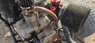
A Dingos Tale part 2

Whitetrashrocker

Inmate #952016
Messages
4,649
Reaction score
3,747
Location
Southern New Mexico
Greywolf. OEM manco? Maybe 92 when these were made if I remember the engine date codes correctly. Refer back to my thread "a tale of 2 dingos" I know I mentioned it.
2 karts from different sources. Engine codes were weeks from each other.

I think I just pushed the limits of crimped pot-metal.
 

Whitetrashrocker

Inmate #952016
Messages
4,649
Reaction score
3,747
Location
Southern New Mexico
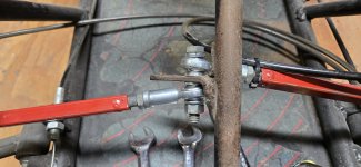
I think these will work.

20251015_184754.jpg

Then I installed them and realized I need some off set spacers.
Some of your keen eye might spot the problem.

Dont have any ⅜tube to make some.
Hmm.
A split washer is pretty thin in that direction and just might be thick enough to make the clearance I need.

Hey lookie, they work.
And now with 4 lock washers it should never come off again.

20251015_192121.jpg

And I just realized. The pitman arm and the steering shaft is the only thing I haven't touched on this one.
 

Hellion

Moderator
Messages
8,530
Reaction score
3,622
I was in a straight away hellion. But I was sliding some corners prior. Its just how I ride.

Yes this was the OEM manco dingo rod end.

View attachment 157170

…..


Soft metal. It just pulled the threads.


I was wondering if, in their cost-cutting mindset, those heim joints were constructed in a way that the threads were pressed into the metal (around a forming die?) instead of cut the old fashioned way. Even cut the old fashioned way it’s still quite economical as it’s two sheet metal halves pressed around the ball joint, lickety-split.

The bore has no threads in the corners due to the almond shape.
 

Edwin Spangler

Well-known member
Messages
829
Reaction score
802
I was wondering if, in their cost-cutting mindset, those heim joints were constructed in a way that the threads were pressed into the metal (around a forming die?) instead of cut the old fashioned way. Even cut the old fashioned way it’s still quite economical as it’s two sheet metal halves pressed around the ball joint, lickety-split.

The bore has no threads in the corners due to the almond shape.
You can tell, whichever way they assemble it, that the threads are cut (or pressed like you say) before the halves are pressed together. The pointy end of the "almond shape" has threads going into it, in a sort of curve, it looks. Looks like the threads are there, they just wont grab anything.

EDIT: Nope I changed my mind. It looks like a threaded insert pressed into each half seperately.
 

Whitetrashrocker

Inmate #952016
Messages
4,649
Reaction score
3,747
Location
Southern New Mexico
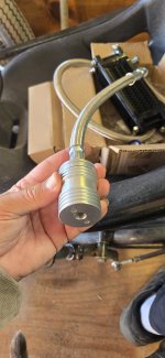
I decided I'd up grade a bit. Add an oil cooler.

20251024_134851.jpg

20251109_161633.jpg

They make 2 kinds for this engine.
One you get a new valve cover that has the pressurized oil passage tapped and the return goes back to the valves.
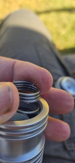
The other, more common, and the cheaper one I got uses a plug that replaces the oil screen just before the pump. Its a Negative pressure system.
Not too keen on that idea, but it works.

20251109_161640.jpg

20251109_161646.jpg

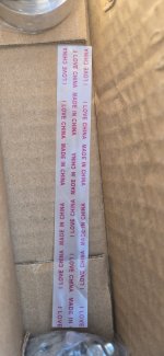
I like the love note they send.

20251024_135431.jpg
 

Whitetrashrocker

Inmate #952016
Messages
4,649
Reaction score
3,747
Location
Southern New Mexico
It replaced the pre pump screen behind this plug.

20251109_161716.jpg

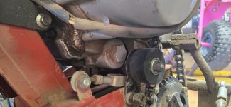
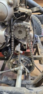
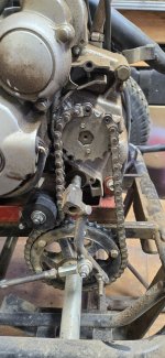
Shouldn't be a problem except i made the chain go a non normal direction. My tensioner is in the way.

20251109_161726.jpg

Here's the new screen filter. Thay made it in line. And of course its all full of machining crud.

20251109_161830.jpg

20251024_135131.jpg
 

Whitetrashrocker

Inmate #952016
Messages
4,649
Reaction score
3,747
Location
Southern New Mexico
Moved the tensioner and added a link to the chain to go from here.

20251109_165039.jpg

To here.

20251109_165055.jpg

Got the new plug installed.

Now I've got to decide where to install the radiator.

Up high.

20251109_190059.jpg

Medium.

20251109_190115.jpg

Or down low.

20251109_190140.jpg
 

Attachments

  • 20251109_190155.jpg
    20251109_190155.jpg
    6.2 MB · Views: 2

Whitetrashrocker

Inmate #952016
Messages
4,649
Reaction score
3,747
Location
Southern New Mexico
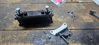
Here's a few more pics of that cooler.
It came with the mounting bracket on the same side as the oil lines.

20251111_174701.jpg

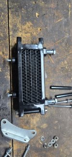
Took it apart and swapped the end plates and made the mount on the bottom.

20251111_174810.jpg

20251111_175244.jpg

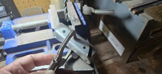
Dug in the scrap bin and found a chunk of angle iron that was just right. Drilled a couple holes.

20251111_181922.jpg

20251111_182035.jpg

A few good tack welds and a squirt of paint.

20251111_184346.jpg

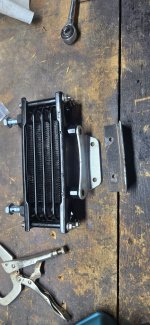
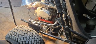
Got it mounted. Filled the cooler and attached the lines. Ran it for a bit and could feel the heat building in the radiator so I felt better about the flow.

20251111_190028.jpg

I decided to put it on this side cause the lines ran better and it was kinda busy on the other side with chain and shift links.

Best part? So far no leaks.

But I still managed to bobble the funnel as I was topping it up and dumped oil all over the brake rotor. Good thing for carb spray.
 

Whitetrashrocker

Inmate #952016
Messages
4,649
Reaction score
3,747
Location
Southern New Mexico
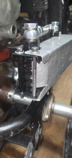
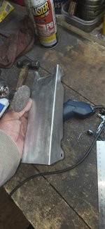
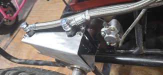
Started making an air scoop for the oil cooler.

20251112_192820.jpg

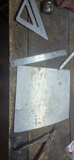
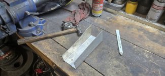
Some flat aluminum i dug up from the pile.

Made some marks and started bending.

20251112_193748.jpg

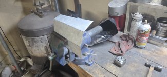
A little more tappy tapp tap and I have a wedge.

20251112_194247.jpg

A bit of trimming and im getting close.

20251112_201506.jpg
 

Whitetrashrocker

Inmate #952016
Messages
4,649
Reaction score
3,747
Location
Southern New Mexico
Update time.
That oil cooler is magnificent. Just touching the return compared to the inlet side is drastic.

Had some family over and zooming around the yard and my 20yo nephew thought he could race me on my own track and karts. Ha.
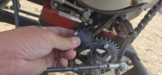
Then the chain jumped off the sprocket and locked it all down.
Wadded up so bad i couldn't rock it back and forth to free some slack. Had to break a chain link to get it untied.

So let's fix the problem. Again.....

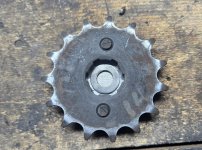
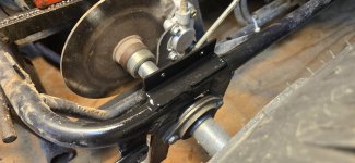
The output shaft has a groove cut in it like for a snap ring. I have to flip my sprocket out board of this ring and lock it in from the inside for clearance issues. The chain wasnt intended to exit downward.
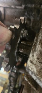
20260327_183928.jpg

I figured id drill and tap the shaft and put a thick washer and bolt to hold the sprocket tight. There's a lot of wiggle the way its made.

20260327_183939.jpg

Nope.
That shaft is harder than a teenage...
I tried drilling with every tool I had.
So off to plan 335 revision 12.

Trace my bolt pattern.
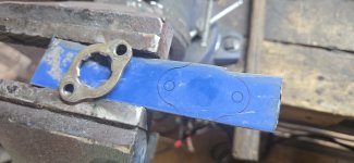
20260327_180418.jpg

Cut it out and make it pretty.

20260327_182844.jpg

Got my measuring stick and this washer will work just right.
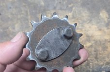
20260327_183003.jpg

20260327_182959.jpg

A little hot glue and I have a button.
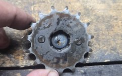
20260327_183543.jpg

20260327_183949.jpg

Bolted on and plenty of chain clearance.

20260327_184410.jpg

The sprocket wiggle no mo.
 

Whitetrashrocker

Inmate #952016
Messages
4,649
Reaction score
3,747
Location
Southern New Mexico
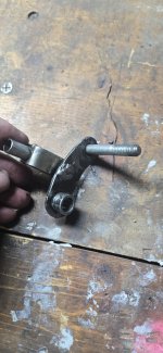
In the chaos of that chain of course it took out the tensioner.
So ive lost count of how many times I've been here.

The thin metal just couldn't hang.
I tried to bend it back but I just knew if it failed once it will fail again.

20260327_195016.jpg


Im still not sure which caused the derailment, the tensioner giving way and the chain went slack, or the sprocket wiggle jumped the chain and the tensioner was just an innocent bystander.

There's a bit of side load the way i made it so im not surprised.

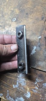
Lets try this reject from another project. Its much thicker and has a curl that will definitely add some rigidity.
And bonus nuts.
In the right spot even.

20260327_195011.jpg

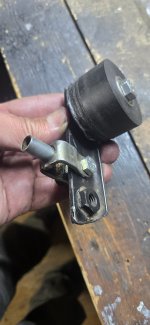
Drill a hole for the push rod and bobs your auntie.

20260327_202457.jpg

Lets see how long this one lasts.

20260327_204902.jpg
 
Top