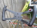
2020 - Excalibur Electric Racing kart

Functional Artist

Well-known member
Messages
5,492
Reaction score
3,074
Location
Toledo, Ohio
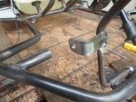
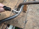
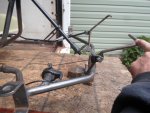
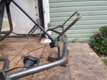
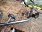
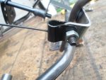
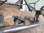
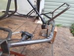
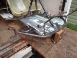
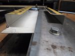
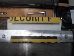
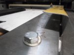
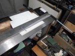
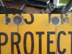
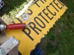
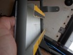
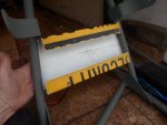
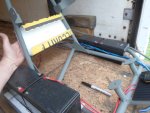
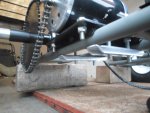
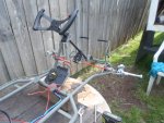
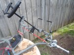
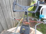
I made the mounting bracket on the pedal a bit "off set" to align with the thumb throttle :thumbsup:

This also, helps to keep the "linkage assembly" further, off to the side
…& "outta harms way" :cheers2:

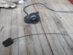
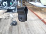
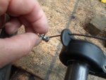
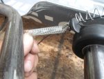
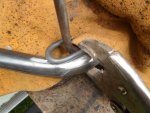
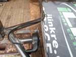
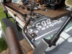
The cable "slides" thru the small hole in the end of the "connector"
...the "barrel head", on the end of the cable, fits in the "loop"
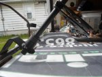
…& a "stop nut", on the other end of the cable, engages/catches the "lever" on the thumb throttle :cool:

The throttle pedal "throw" seems to be ~3" :2guns:
 

Attachments

  • SAM_4876.JPG
    SAM_4876.JPG
    310.3 KB · Views: 3
  • SAM_4877.JPG
    SAM_4877.JPG
    308.8 KB · Views: 4
  • SAM_4878.JPG
    SAM_4878.JPG
    314.9 KB · Views: 3
  • SAM_4879.JPG
    SAM_4879.JPG
    312.6 KB · Views: 3
  • SAM_4880.JPG
    SAM_4880.JPG
    316 KB · Views: 4
  • SAM_4899.JPG
    SAM_4899.JPG
    312.7 KB · Views: 3
  • SAM_4895.JPG
    SAM_4895.JPG
    320.1 KB · Views: 3
  • SAM_4892.JPG
    SAM_4892.JPG
    311.1 KB · Views: 4
  • SAM_4888.JPG
    SAM_4888.JPG
    314.6 KB · Views: 3
  • SAM_4881.JPG
    SAM_4881.JPG
    323.4 KB · Views: 3
Functional Artist

Well-known member
Messages
5,492
Reaction score
3,074
Location
Toledo, Ohio
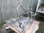
I tried a spring "in-between" the pedal & thumb throttle
...but, it was still kinda "floppy"

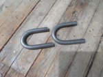
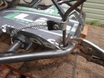
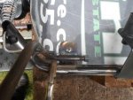
So, I bent a couple of pieces of 1/4" rod into a U shape
...to use as/for "pedal stops" :thumbsup:

The brake doesn't seem to need one
...but, the throttle was kinda floppy (when released)
…& also, the pedal could put "too much" pressure, on the thumb throttle, when "floored" or fully applied :huh:

Yup, she's good-n-solid now (in both directions) :wai:
…& no "pressure" on the thumb throttle (it's just "along for the ride") :cool:
 

Attachments

  • SAM_4905.JPG
    SAM_4905.JPG
    315.1 KB · Views: 2
  • SAM_4906.JPG
    SAM_4906.JPG
    316.7 KB · Views: 2
  • SAM_4909.JPG
    SAM_4909.JPG
    312 KB · Views: 2
  • SAM_4910.JPG
    SAM_4910.JPG
    314 KB · Views: 2
  • SAM_4911.JPG
    SAM_4911.JPG
    308.2 KB · Views: 2
  • SAM_4919.JPG
    SAM_4919.JPG
    313.5 KB · Views: 4
  • SAM_4917.JPG
    SAM_4917.JPG
    315.3 KB · Views: 2
  • SAM_4916.JPG
    SAM_4916.JPG
    315.3 KB · Views: 1
  • SAM_4908.JPG
    SAM_4908.JPG
    314.4 KB · Views: 2
  • SAM_4913.JPG
    SAM_4913.JPG
    315.1 KB · Views: 2

Functional Artist

Well-known member
Messages
5,492
Reaction score
3,074
Location
Toledo, Ohio
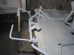
I re-installed the floorboard, steering assembly & seat again
…so, I could actually/physically, get in/sit down & make sure everything "worked together" :thumbsup:

The seat feels comfortable
...& firm

The steering height
...& distance from driver seems good

The brake pedal/action is super firm
...& it "would/should "stop on a dime"

The throttle pedal is not difficult to actuate (sometimes springs are kinda "stiff" just before "stretching")
…it returns/springs back nicely
…the petal positions seem good too
(from zero throttle thru full throttle the drivers foot is not in an awkward position)
…& the thumb throttle (electronic component) seems safe "tucked" off to the side :cheers2:
 

Attachments

  • SAM_4900.JPG
    SAM_4900.JPG
    315.9 KB · Views: 6
  • SAM_4901.JPG
    SAM_4901.JPG
    310.4 KB · Views: 3
  • SAM_4902.JPG
    SAM_4902.JPG
    313.4 KB · Views: 3
  • SAM_4903.JPG
    SAM_4903.JPG
    309.8 KB · Views: 4

Functional Artist

Well-known member
Messages
5,492
Reaction score
3,074
Location
Toledo, Ohio
It looks good to me!

Thanks! :thumbsup:

It's been kinda rainy & humid lately :huh:
…& we got a lot of "bare" metal "exposed"

I guess it's time to "seal 'er up" :wai:

So, I took 'er all back apart again
…meticulously smoothed & cleaned every piece (every "nook-n-cranny")
…& wiped 'er down/gave 'er a "bath" in paint thinner :2guns:

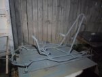
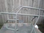
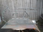
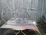
Then, sprayed a good coat of Self Etching Primer
...looks kinda "faded" Army Green
...or even Olive Drab (Hawkeye-M*A*S*H*) :cheers2:
 

Attachments

  • SAM_4934.JPG
    SAM_4934.JPG
    311.7 KB · Views: 4
  • SAM_4933.JPG
    SAM_4933.JPG
    307.2 KB · Views: 2
  • SAM_4932.JPG
    SAM_4932.JPG
    313.6 KB · Views: 3
  • SAM_4930.JPG
    SAM_4930.JPG
    312.7 KB · Views: 2
  • SAM_4929.JPG
    SAM_4929.JPG
    313.6 KB · Views: 3
  • SAM_4936.JPG
    SAM_4936.JPG
    315.5 KB · Views: 2

Functional Artist

Well-known member
Messages
5,492
Reaction score
3,074
Location
Toledo, Ohio
While the primer was dryin', on the chassis, I started roundin' up electrical components
…& made up a dash board :thumbsup:

It'll have a circuit breaker/main cut-off switch
...the on/off switch
…& the forward reverse switch :cheers2:

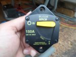
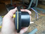
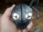
Ima gonna use a 48V 150A Buss MRCB circuit breaker as both a "resettable" fuse
…& the main cut-off switch

A "rocker style" switch will activate/turn on or off the speed controller

The "duck bill" switch will "signal" to the speed controller the, drivers, "intended direction of travel"

* Flipped forward, indicates ya wanna to go forward
...& "flipped" toward the back will "reverse" the direction of travel :2guns:
 

Attachments

  • SAM_4963.JPG
    SAM_4963.JPG
    312.2 KB · Views: 5
  • SAM_4953.JPG
    SAM_4953.JPG
    315.2 KB · Views: 4
  • SAM_4961.JPG
    SAM_4961.JPG
    319.4 KB · Views: 4
  • SAM_4960.JPG
    SAM_4960.JPG
    305.9 KB · Views: 3
  • SAM_4959.JPG
    SAM_4959.JPG
    313.9 KB · Views: 3

Functional Artist

Well-known member
Messages
5,492
Reaction score
3,074
Location
Toledo, Ohio
Power Wires

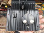
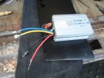
The leads coming out of the SC (speed controller) for a 48V 1,000W motor use big (~10g.) wires for the "power wires", these bring the "power in" from the battery (+/-) & also, to send "power out" to the motor (+/-)
…& then, they use smaller (~20g.) wires to send/receive "signals", like on/off & reverse :thumbsup:

To use for the "power wires", I got some red (10g.) wire for the positive (+) side
…& some black (10g.) wire to connect the negative (-) side

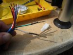
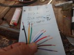
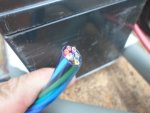
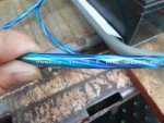
For the "signal wires" I got a kool lookin', blue "cable" that has (9) individual/colored (20g.) wires within it

I figured, I'd "run" the bigger "power wires" first (more cumbersome)
…& then, "run" the smaller "signal wires" (easier to "tuck in") :cheers2:

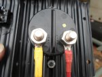
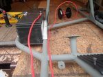
So, starting @ the front right batteries positive (+) terminal, I ran a piece of the red "power" wire from it, to the "Line" side of the CB (circuit breaker)
…& then, ran another piece from the, "Load" side of the CB to the SC

* The electrical "current" must flow in the designated direction, thru the CB, for it to "function" properly :cool:

** Since both of these wires, look/are the same
…will "run" down the right side of the kart
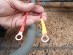
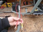
...& will also, connect to the CB, I "color coded" the ends, to easily indicate which one is the "power in" (red) coming from the battery
...& which one is the "power out" (yellow) going to the SC :2guns:
 

Attachments

  • SAM_4955.JPG
    SAM_4955.JPG
    311.2 KB · Views: 2
  • SAM_4956.JPG
    SAM_4956.JPG
    310.5 KB · Views: 2
  • SAM_4964.JPG
    SAM_4964.JPG
    317.6 KB · Views: 2
  • SAM_4967.JPG
    SAM_4967.JPG
    316.7 KB · Views: 2
  • SAM_4976.JPG
    SAM_4976.JPG
    318.3 KB · Views: 3
  • SAM_4977.JPG
    SAM_4977.JPG
    318.1 KB · Views: 3
  • SAM_4973.JPG
    SAM_4973.JPG
    317.6 KB · Views: 2
  • SAM_4972.JPG
    SAM_4972.JPG
    314.2 KB · Views: 1
  • SAM_4971.JPG
    SAM_4971.JPG
    311.6 KB · Views: 3

Functional Artist

Well-known member
Messages
5,492
Reaction score
3,074
Location
Toledo, Ohio
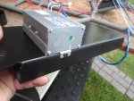
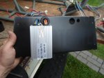
Before "runnin' the signal wires, from the dash board to the SC (speed controller)
...we gotta figure out how & where we are gonna mount the SC :thumbsup:

* We also gotta keep in mind that "test #2" will use (2) motors
...which means we gotta provide mounting "space" for (2) SC's :cheers2:

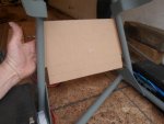
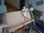
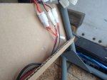
So, I was thinkin' to just mount a "panel" across the "roll bar/seat back" right behind the seat
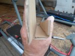
….takin' it a "step further", I figured I could kinda "box in" the bottom, to protect & support the plugs & connections
…& then, I figured why not "box in" the top too :2guns:

* This "double boxing" will make for a good-n-strong "structure"
...so, it can be made from lighter materials :wai:

So, I'ma gonna try-n-make it outta some 16g. aluminum (same as the floor board & battery trays) :cool:
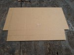
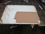
...but, first I made a "test piece" outta some cardboard ;)

** I even folded/bent it in the sheet metal bender, for nice-n-crisp fold/bend lines

Yup, that should work :sifone:
...just gotta make 'er outta metal now :popcorn:
 

Attachments

  • SAM_4996.JPG
    SAM_4996.JPG
    312.7 KB · Views: 1
  • SAM_4995.JPG
    SAM_4995.JPG
    309.9 KB · Views: 1
  • SAM_4994.JPG
    SAM_4994.JPG
    316.5 KB · Views: 1
  • SAM_4993.JPG
    SAM_4993.JPG
    313.7 KB · Views: 1
  • SAM_4992.JPG
    SAM_4992.JPG
    310.6 KB · Views: 1
  • SAM_5002.JPG
    SAM_5002.JPG
    313.4 KB · Views: 1
  • SAM_5004.JPG
    SAM_5004.JPG
    319.7 KB · Views: 2
  • SAM_5006.JPG
    SAM_5006.JPG
    314 KB · Views: 2
  • SAM_5008.JPG
    SAM_5008.JPG
    312.6 KB · Views: 2
  • SAM_5012.JPG
    SAM_5012.JPG
    312.5 KB · Views: 1

Functional Artist

Well-known member
Messages
5,492
Reaction score
3,074
Location
Toledo, Ohio
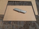
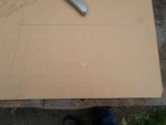
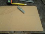
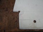
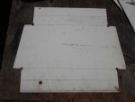
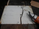
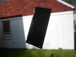
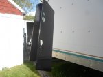
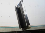
Next, I used the card board "mock up" as a template to mark the metal (another old sign) :thumbsup:

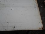
* Before cuttin', I drilled some holes where the inside cuts will intersect (for nice/clean "inner" corners) :cheers2:

Smoothed/deburred the edges, a bit :cool:
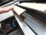
…& then, took 'er to the bender

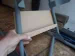
1 1/2" from top bend to 90*
...then, slide 'er out another 1 1/2"
...& then, bend 'er to 90* again

For the bottom, I flipped 'er around
…& simply, repeated the procedure :2guns:
 

Attachments

  • SAM_5026.JPG
    SAM_5026.JPG
    312.2 KB · Views: 3
  • SAM_5024.JPG
    SAM_5024.JPG
    301.6 KB · Views: 4
  • SAM_5021.JPG
    SAM_5021.JPG
    318.5 KB · Views: 3
  • SAM_5019.JPG
    SAM_5019.JPG
    292.6 KB · Views: 3
  • SAM_5013.JPG
    SAM_5013.JPG
    306.9 KB · Views: 3
  • SAM_5044.JPG
    SAM_5044.JPG
    312.1 KB · Views: 3
  • SAM_5043.JPG
    SAM_5043.JPG
    307.3 KB · Views: 3
  • SAM_5037.JPG
    SAM_5037.JPG
    310 KB · Views: 4
  • SAM_5030.JPG
    SAM_5030.JPG
    313.6 KB · Views: 4
  • SAM_5029.JPG
    SAM_5029.JPG
    314.3 KB · Views: 4

Functional Artist

Well-known member
Messages
5,492
Reaction score
3,074
Location
Toledo, Ohio
Did a quick test fit
…& added some screw holes for mounting :thumbsup:

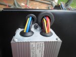
Before paintin', I had to drill some holes to "run" the plugs/wires thru

The big ~1" hole is for the "signal" wires
…& the smaller ~3/8" hole is for the "power" wires :cool:

* I went ahead & drilled the holes, to "run" the plugs/wires thru, for SC #2
...but, they should have been the same on both sides :huh:

Both of the small holes should have been on the left
...& both big holes should have been on the right :mad2:
** Noticed it, while it was dryin' :smiley_omg:
Oh well, I'll deal with it later :2guns:
 

Attachments

  • SAM_5052.JPG
    SAM_5052.JPG
    315 KB · Views: 2
  • SAM_5049.JPG
    SAM_5049.JPG
    315.8 KB · Views: 2
  • SAM_5048.JPG
    SAM_5048.JPG
    312.5 KB · Views: 2
  • SAM_5046.JPG
    SAM_5046.JPG
    316 KB · Views: 2
  • SAM_5045.JPG
    SAM_5045.JPG
    314.3 KB · Views: 3
  • SAM_5054.JPG
    SAM_5054.JPG
    298.8 KB · Views: 3
  • SAM_5055.JPG
    SAM_5055.JPG
    306.3 KB · Views: 3
  • SAM_5057.JPG
    SAM_5057.JPG
    304.7 KB · Views: 4
  • SAM_5058.JPG
    SAM_5058.JPG
    289.8 KB · Views: 3

Functional Artist

Well-known member
Messages
5,492
Reaction score
3,074
Location
Toledo, Ohio
I popped a 3/8" rubber grommet into (1) of the small holes
…& a 3/4" grommet into (1) of the big holes :thumbsup:

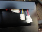
Then, poked the wires/plugs thru
…& used a couple of screws to "bolt 'er down" :cheers2:

Nice-n-clean "look"
…plus, good-n-sturdy :2guns:

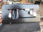
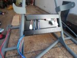
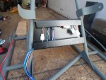
The connections will be protected from "all" sides
…& there's also, easy access by either removing (4) screws & tilting the panel
...or by removing the seat :cool:
 

Attachments

  • SAM_5069.JPG
    SAM_5069.JPG
    319.7 KB · Views: 5
  • SAM_5068.JPG
    SAM_5068.JPG
    310.4 KB · Views: 5
  • SAM_5067.JPG
    SAM_5067.JPG
    319.8 KB · Views: 4
  • SAM_5066.JPG
    SAM_5066.JPG
    310 KB · Views: 3
  • SAM_5065.JPG
    SAM_5065.JPG
    308.8 KB · Views: 3
  • SAM_5070.JPG
    SAM_5070.JPG
    311 KB · Views: 3
  • SAM_5071.JPG
    SAM_5071.JPG
    305.5 KB · Views: 5
  • SAM_5073.JPG
    SAM_5073.JPG
    315.3 KB · Views: 6

Functional Artist

Well-known member
Messages
5,492
Reaction score
3,074
Location
Toledo, Ohio
Thanks fellas :thumbsup:

So, I "ran" the kool blue (9) wire harness to the rear "connection box"
…& connected the wires to their corresponding plugs :cheers2:

Also, I think I came up with a clever idea for protecting, insulating & mounting the shunt
...for the PZEM-051 (100V 100A) electrical monitoring system :wai:

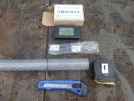
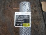
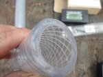
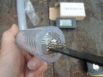
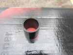
I got some 1" vinyl tube (with some kool braiding)
…& simply "slid" the shunt inside (fits nice-n-tight) :cool:

Then, it can easily be mounted to the bottom of the "connection box" :2guns:
 

Attachments

  • SAM_5073.JPG
    SAM_5073.JPG
    315.3 KB · Views: 4
  • SAM_5060.JPG
    SAM_5060.JPG
    314 KB · Views: 3
  • SAM_5059.JPG
    SAM_5059.JPG
    315.7 KB · Views: 3
  • SAM_4988.JPG
    SAM_4988.JPG
    313.8 KB · Views: 4
  • SAM_4987.JPG
    SAM_4987.JPG
    314.6 KB · Views: 4
  • SAM_4937.JPG
    SAM_4937.JPG
    311.7 KB · Views: 4
  • SAM_4939.JPG
    SAM_4939.JPG
    316.7 KB · Views: 6
  • SAM_4940.JPG
    SAM_4940.JPG
    317.2 KB · Views: 4
  • SAM_4942.JPG
    SAM_4942.JPG
    312.2 KB · Views: 4
  • SAM_5074.JPG
    SAM_5074.JPG
    313.3 KB · Views: 5

Functional Artist

Well-known member
Messages
5,492
Reaction score
3,074
Location
Toledo, Ohio
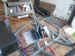
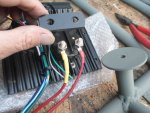
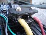
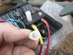
Finishin' up the wiring :thumbsup:

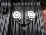
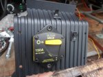
I didn't like the "open terminals" on them "big" power wires :huh:
...so, I covered 'em up :cheers2:
 

Attachments

  • SAM_5087.JPG
    SAM_5087.JPG
    316.8 KB · Views: 3
  • SAM_5085.JPG
    SAM_5085.JPG
    316.3 KB · Views: 3
  • SAM_5084.JPG
    SAM_5084.JPG
    315.9 KB · Views: 3
  • SAM_5083.JPG
    SAM_5083.JPG
    317.3 KB · Views: 3
  • SAM_5081.JPG
    SAM_5081.JPG
    319.2 KB · Views: 3
  • SAM_5088.JPG
    SAM_5088.JPG
    316.8 KB · Views: 3
  • SAM_5090.JPG
    SAM_5090.JPG
    318.3 KB · Views: 3
  • SAM_5091.JPG
    SAM_5091.JPG
    313.8 KB · Views: 3
  • SAM_5098.JPG
    SAM_5098.JPG
    315.4 KB · Views: 3
  • SAM_5099.JPG
    SAM_5099.JPG
    316.7 KB · Views: 3
Functional Artist

Well-known member
Messages
5,492
Reaction score
3,074
Location
Toledo, Ohio
Tidying up some "small stuff"

I measured, marked & cut some "spacers" (1) for between the sprocket & bearing
...& (1) for between the sprocket & wheel

Also, (1) "spacer" for between the brake drum & bearing
…& (1) for between the brake drum & wheel

Then, cleaned 'em up & sprayed 'em satin black :thumbsup:

* To be able to "tell" the difference between the (2) "spacers" for the left & the (2) for the right, I marked the (2) for the left side with a small "notch" :cheers2:

While they were dryin' I started some re-assembly :wai:

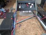
I installed the "trays" (1) on each side
...& the batteries (2) on each side :2guns:
 

Attachments

  • SAM_5107.JPG
    SAM_5107.JPG
    311 KB · Views: 4
  • SAM_5110.JPG
    SAM_5110.JPG
    305.3 KB · Views: 4
  • SAM_5109.JPG
    SAM_5109.JPG
    305.7 KB · Views: 3
  • SAM_5108.JPG
    SAM_5108.JPG
    304.6 KB · Views: 3
  • SAM_5100.JPG
    SAM_5100.JPG
    314.4 KB · Views: 4
  • SAM_5102.JPG
    SAM_5102.JPG
    315.8 KB · Views: 4
  • SAM_5103.JPG
    SAM_5103.JPG
    312 KB · Views: 5

Functional Artist

Well-known member
Messages
5,492
Reaction score
3,074
Location
Toledo, Ohio
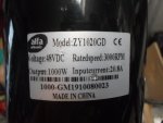
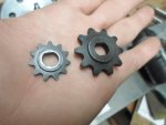
Before mounting (1) of the ZY-1020 motors, I had ta "switch" the drive sprocket
...from the one that came on it (for #25 chain)
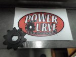
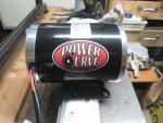
...over to a Power Curve Sprocket (for a #35 chain) :cheers2:

* Remember the bolt, that hold's the sprocket on these motors, have left-hand or "reverse" threads :thumbsup:

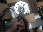
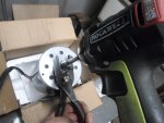
I used a pair of plyers (opened "up big") to "grip" the sprocket
…& an impact driver, to remove the bolt :cool:

Then, reversed the procedure, to install the "new" one :2guns:
(he he, double reverse) :smiley_omg:
Also, installed the sticker :D
...gotta "represent" :sifone:
 

Attachments

  • SAM_5118.JPG
    SAM_5118.JPG
    316.4 KB · Views: 6
  • SAM_5116.JPG
    SAM_5116.JPG
    314 KB · Views: 5
  • SAM_5114.JPG
    SAM_5114.JPG
    310 KB · Views: 6
  • SAM_5113.JPG
    SAM_5113.JPG
    317.3 KB · Views: 7
  • SAM_5111.JPG
    SAM_5111.JPG
    313.5 KB · Views: 7
  • SAM_5120.JPG
    SAM_5120.JPG
    309.1 KB · Views: 5
  • SAM_5121.JPG
    SAM_5121.JPG
    315.1 KB · Views: 5
  • SAM_5123.JPG
    SAM_5123.JPG
    314.2 KB · Views: 5
  • SAM_5127.JPG
    SAM_5127.JPG
    313.4 KB · Views: 7
  • SAM_5133.JPG
    SAM_5133.JPG
    320.5 KB · Views: 6

Functional Artist

Well-known member
Messages
5,492
Reaction score
3,074
Location
Toledo, Ohio
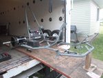
I "mounted" the motor on the mount (version #1)
…& then, "mounted" 'em on the kart :thumbsup:

*notice the kool black "spacers" :cheers2:

Then, I brought 'er out & put 'er on the worktable (ta get 'er used to the outdoors) :cool:
…& started re-installing the steering components :2guns:
 

Attachments

  • SAM_5134.JPG
    SAM_5134.JPG
    316.7 KB · Views: 9
  • SAM_5136.JPG
    SAM_5136.JPG
    311.6 KB · Views: 10
  • SAM_5141.JPG
    SAM_5141.JPG
    309.1 KB · Views: 9
  • SAM_5142.JPG
    SAM_5142.JPG
    312.2 KB · Views: 9
  • SAM_5146.JPG
    SAM_5146.JPG
    312.4 KB · Views: 8
  • SAM_5145.JPG
    SAM_5145.JPG
    311.6 KB · Views: 8
Top