Mrturbo458
New member
- Messages
- 106
- Reaction score
- 0
Nope, I will upon final assembly though. Just in case I need to take it apart or change something. We're a ways off from loctite assembly, sadly. Haha

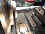

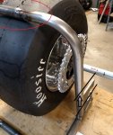

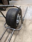
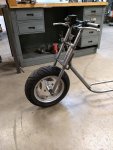
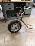
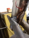
This gap will solve the clearance issue...
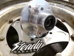
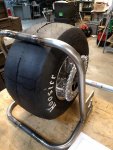
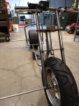
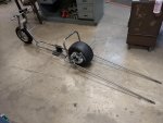
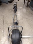
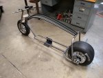
Ez is correct. If you look at where the bearing mount is, you'll see that it's about 9" (18" tall tire) lower (on center) than the mock up axle. The picture is showing width, primarily.
-MrTurbo

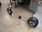
 sadly.... I picked up double the hours at work (good for money, bad for extra time) so I'm super busy. But I am still working on the mini bike, and I'm making a little bit of progress.
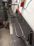
I am thinking custom fab'ed I-beam.
