They can be merged, but if i remember correctly all the posts get added in date order, so this post will be at the bottom somewhere. Let us know though what you want
You are using an out of date browser. It may not display this or other websites correctly.
You should upgrade or use an alternative browser.
You should upgrade or use an alternative browser.
2017 - Hero (Zero Turn Go Kart)
- Thread starter Functional Artist
- Start date
- Status
- Not open for further replies.
Functional Artist
Well-known member
That's fine.
I just wanted to include all of the build info.
Thanks,
Now, on to finish this kart.
I just wanted to include all of the build info.
Thanks,
Now, on to finish this kart.
Functional Artist
Well-known member
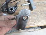
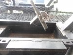
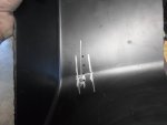
I started workin' on the hand controls today.
I had to do some trimmin' because I couldn't get a enough swing of the control lever for the thumb throttle to accelerate all the way & also back enough to engage the brake.
I want the controls to be spring loaded:
to stand straight up when in neutral. (not accelerating or braking)
pull back ~1/4" to engage the brake
push forward from ~1/4" to 1" to accelerate.
Well give that a try.
Attachments
-
 SAM_3117.jpg231.6 KB · Views: 3
 -
 SAM_3122.jpg218.6 KB · Views: 4
 -
 SAM_3128.jpg234.9 KB · Views: 3
 -
 SAM_3121.jpg276.8 KB · Views: 3
Bbqjoe
Banned
I would like to officially enter Hero, my Zero Turn Go Kart in the 2017 Build Off.
Time to get this project rolling again.
I have been gathering stuff but, I haven't worked on it since my last post 1/8/2017
I not sure how this works but, can that build info be merged with this new thread?

Cool. But where do you light it?

Functional Artist
Well-known member
Cool. But where do you light it?
No need to light it.
No internal combustion goin' on here.
No need to start it.
No smelly fuel.
No hot exhaust.
Just push a button & go.
All electronic.
Instant torque.
Instant power
Functional Artist
Well-known member
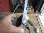
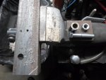
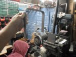
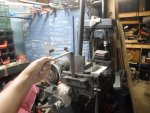
Worked on installing the right control lever today.
It had to be
...angled right to function as designed (neutral: lever straight up)
...the right height to be comfortable to use while driving
...to line up with the curve at the front of each arm rest to take advantage of the extra radius area for our control handle.
Once I determined the proper position & placement, I drilled a couple of 1/8" holes & temporarily mounted it with sheet metal screws.
Attachments
-
 SAM_3149.jpg195.2 KB · Views: 2
 -
 SAM_3153.jpg217.2 KB · Views: 2
Functional Artist
Well-known member
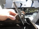
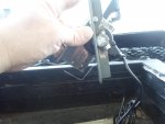
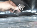
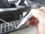
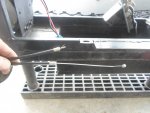
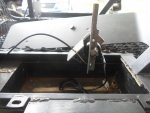
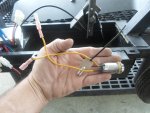
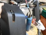
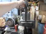
Next was the brake cable.
I figured the smoothest routing path from the hand control to the brake on the rear wheel.
Marked the cable with silver marker & pulled the inner cable almost all the way out before cutting.
Mounted the waste piece into the vise & used our handy dandy cut off tool to cleanly whack it off.
Used a dab (huh huh, I said dab) of super glue on the freshly cut inner cable end to prevent fraying.
Attachments
-
 SAM_3170.jpg265.3 KB · Views: 2
 -
 SAM_3166.jpg239.5 KB · Views: 2
 -
 SAM_3156.jpg265.1 KB · Views: 2
 -
 SAM_3157.jpg252.9 KB · Views: 2
Functional Artist
Well-known member
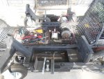
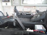
The right hand control is mounted in place with:
...the thumb throttle
...the brake cable
...the motor & chain
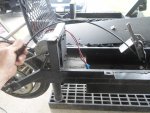
Next is the right motor/speed controller.
Bolted it down in the box under the right arm rest.
Using the supplied wiring diagram,
I hooked up the motor wires first,
The motor wires from the motor were red & black.
The motor wires from the controller were yellow & blue.
I would assume red to yellow & black to blue.
No big deal, if I'm wrong it will just go backwards.
Next is the thumb throttle:
that's simple enough it's the only plug with three wires.
But, wait the wires don't match up.
Back to the controller diagram.
OK, red is the power wire.
Check, there is a red wire on both the throttle plug end & on the controller plug end.
OK, black is the ground wire.
Yup, we got a black wire on both.
So that means that the third wire is the signal wire.
The third wire on the thumb throttle is blue & it's white from the controller.
We can pretty confidently hook them together now that we have used deductive reasoning to determine what each of the wires do.
We wont be using:
the charging port plug (We charge directly to battery pack)
brake cut-off plug (with this design you can't accelerate & brake at the same time)
The only other things I need to hook up is a key/on-off switch to turn the system on & off & the battery pack.
Well, lets give it a try.
https://www.youtube.com/watch?v=BtvCmnGFIlI&t=74s
...the thumb throttle
...the brake cable
...the motor & chain
Next is the right motor/speed controller.
Bolted it down in the box under the right arm rest.
Using the supplied wiring diagram,
I hooked up the motor wires first,
The motor wires from the motor were red & black.
The motor wires from the controller were yellow & blue.
I would assume red to yellow & black to blue.
No big deal, if I'm wrong it will just go backwards.
Next is the thumb throttle:
that's simple enough it's the only plug with three wires.
But, wait the wires don't match up.
Back to the controller diagram.
OK, red is the power wire.
Check, there is a red wire on both the throttle plug end & on the controller plug end.
OK, black is the ground wire.
Yup, we got a black wire on both.
So that means that the third wire is the signal wire.
The third wire on the thumb throttle is blue & it's white from the controller.
We can pretty confidently hook them together now that we have used deductive reasoning to determine what each of the wires do.
We wont be using:
the charging port plug (We charge directly to battery pack)
brake cut-off plug (with this design you can't accelerate & brake at the same time)
The only other things I need to hook up is a key/on-off switch to turn the system on & off & the battery pack.
Well, lets give it a try.
https://www.youtube.com/watch?v=BtvCmnGFIlI&t=74s
Attachments
-
 SAM_3163.jpg280.2 KB · Views: 1
 -
 SAM_3172.jpg238.2 KB · Views: 1
 -
 SAM_3175.jpg256.2 KB · Views: 1
Functional Artist
Well-known member
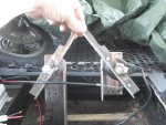
Worked on the left hand control next.
I needs to be exactly the same but, exactly opposite of the right hand control.
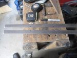
Last fall when I made the parts for the right hand control lever, I also cut the lever arm, the throttle mount with brass bushing inserted & a piece of 2" x 2" angle ~4" long to mount everything to.
I referred back to my note book but, I didn't have many notations just concept drawings.
Then I went back to my digital notebook (DIYGK) & reread my earlier thread that I posted about making the right hand controller.
Very helpful!
The piece of angle iron on the right hand controller was a little on the short side, so I rounded up a longer piece.
Then I did some markin' & drillin' & cuttin' & weldin'.
Yup!, pretty close.
I needs to be exactly the same but, exactly opposite of the right hand control.
Last fall when I made the parts for the right hand control lever, I also cut the lever arm, the throttle mount with brass bushing inserted & a piece of 2" x 2" angle ~4" long to mount everything to.
I referred back to my note book but, I didn't have many notations just concept drawings.
Then I went back to my digital notebook (DIYGK) & reread my earlier thread that I posted about making the right hand controller.
Very helpful!
The piece of angle iron on the right hand controller was a little on the short side, so I rounded up a longer piece.
Then I did some markin' & drillin' & cuttin' & weldin'.
Yup!, pretty close.
Attachments
-
 SAM_3189.jpg398.6 KB · Views: 2
 -
 SAM_3190.jpg252.2 KB · Views: 2
 -
 SAM_3193.jpg236.4 KB · Views: 2
 -
 SAM_3201.jpg278.6 KB · Views: 2
Functional Artist
Well-known member
Left hand controlled is mounted, wired & brake cabled.
Had to use a couple of 3/8" nuts as spacers between the hand control unit & the frame because the housing where the wiring harness attaches to the thumb throttle takes a 90* turn right into the frame rail.
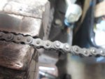
Next, I been lookin' for like 3 days, I can't find one of the drive chains.
The only one I could find was a little too short.
Must be from a 24 volt scooter. The sprocket on the wheel is a little smaller on them.
I found that you can't find that little dinky #25 chain just anywhere.
I finally found a cycle shop that carried it.
Wow! $4.00 a foot (needed just under 3 ft.) plus $1.95 for that little dinky master link.
Workin' with that little dinky chain ain't no fun either.
The pins on this chain are too small for bicycle chain breakers and even worse trying to use the bigger universal breaker.
Hafta go ta Plan B.
Had to use a couple of 3/8" nuts as spacers between the hand control unit & the frame because the housing where the wiring harness attaches to the thumb throttle takes a 90* turn right into the frame rail.
Next, I been lookin' for like 3 days, I can't find one of the drive chains.
The only one I could find was a little too short.
Must be from a 24 volt scooter. The sprocket on the wheel is a little smaller on them.
I found that you can't find that little dinky #25 chain just anywhere.
I finally found a cycle shop that carried it.
Wow! $4.00 a foot (needed just under 3 ft.) plus $1.95 for that little dinky master link.
Workin' with that little dinky chain ain't no fun either.
The pins on this chain are too small for bicycle chain breakers and even worse trying to use the bigger universal breaker.
Hafta go ta Plan B.
Attachments
-
 SAM_3205.jpg261.2 KB · Views: 3
Functional Artist
Well-known member
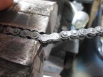
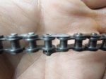
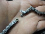
Plan B:
...use our handy dandy cutoff tool to lightly grind off the tops of both pins of the link that needs to be removed.
...used a fine tip regular screwdriver to gently pry the link up & needle nose plyers to twist it off to the side.
Installing that little dinky master link wasn't no fun either.
Left chain is on.
Attachments
-
 SAM_3223.jpg199 KB · Views: 2
 -
 SAM_3227.jpg214 KB · Views: 2
 -
 SAM_3229.jpg206.8 KB · Views: 2
 -
 SAM_3231.jpg188.5 KB · Views: 2
Whitetrashrocker
Inmate #952016
You make it sound like your working with jewers chain.
Need more
Grind, punch, grunt, grunt.
I'm digging what your doing, carry on.
Need more
Grind, punch, grunt, grunt.
I'm digging what your doing, carry on.
Functional Artist
Well-known member
You make it sound like your working with jewers chain.
Need more
Grind, punch, grunt, grunt.
I'm digging what your doing, carry on.
Thanks,
I'm not sure if this chain can take much grind, punch, grunt, grunt.
What's jewers chain?
If your talkin' about jewelers chain, yup
it's kinda like that.If it was gold plated it's similar to what Mr. T would wear it.
Whitetrashrocker
Inmate #952016
Yup that's what I mean tiny stuff.
Functional Artist
Well-known member
After the individual tests on each side,
I wired both controllers to (1) key switch so we have just a master switch.
& the (3) batteries are in series to provide the required 36 volts & are wired to both controllers.
Well, now that both sides are functional, it's time for the first test.
Lets see if this concept works.
https://www.youtube.com/watch?v=0IbvwDhMks4&t=146s
Functional Artist
Well-known member
Yup, it works.
It goes, it turns & it stops but, we have some issues.
1. The right motor does not seem as strong as the left motor.
Original theory: each motor should equally power each side.
On the first test runs, to successfully go straight, I needed to start off & constantly run the right motor & only kick in the left motor to increase speed or for steering correction.
When I tried (or Desteny, in the video) to take off from a stop using both controls (as it should be) the kart would keep pulling to the right.
2. I noticed, that when just pushing the kart by hand, it also pulls to the right.
For these initial tests, I used (3) 12v/12ah scooter batteries from (1) of the scooters to run both motors.
It seemed to last quite a while.
Desteny rode for ~15 minutes.
I went around front here a little while figuring out the controls then went around (4) city blocks (5) or (6) times.
Probably like 20 minutes so, over 1/2 hour of actual run time.
Toward the end, It wasn't quite as zippy but, it wasn't dead.
The batteries, wiring & controllers were all cool to the touch.
I charged but, didn't check the battery pack before our test runs.
After our test runs, I checked the battery pack, it tested @ 37.2v.
After ~(6) hours of charging they tested @ 42.8v.
3. Motor temp: the left motor was warm but, the right motor was noticeably warmer.
Causes could be;
1. Right motor is more warn.
2. Using right motor more during the test run to compensate for steering.
3. gear ratio issue.
Functional Artist
Well-known member
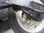
Switched the motors today, as a test, to help diagnose the unequal power issue.
Odd thing was, that when I switched the motors the chain on the right motor was super tight & the chain on the left motor was very loose.
I did not loosen rear wheels, just unbolted the motors.
Well, maybe one has an extra tooth.
That would not make sense, these things are mass produced & both motors & both rear wheels look identical.
To be sure I counted. (all them little teeth)
Both motors have 11 tooth sprockets & both rear wheels have 80 tooth sprockets.
Everything still seems identical.
IDK?
Adjust chains to proper tension & move on to testing.
https://www.youtube.com/watch?v=24BQB28crMc
Functional Artist
Well-known member
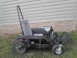
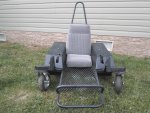
Second test drive did better.
Switching the motors helped a bit, but
It still has issues
It still doesn't function 100% properly, but
I'm learning how to work it. (or make it work)
Well, let's move on.
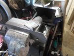
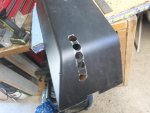
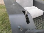
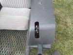
Worked on the arm rests today.
First, I placed the arm rests partially in place to mark where the hand control lever will protrude.
Then, drilled a series of holes centered along our mark.
I started with an 1/8" bit then 3/16" then 1/4" then 5/16" then 3/8" then 1/2" and finally 1".
Then I used an old knife & a propane torch to (hot knife) thru the plastic to connect the dots.
Still need some work.
Makin' progress.
Switching the motors helped a bit, but
It still has issues
It still doesn't function 100% properly, but
I'm learning how to work it. (or make it work)
Well, let's move on.
Worked on the arm rests today.
First, I placed the arm rests partially in place to mark where the hand control lever will protrude.
Then, drilled a series of holes centered along our mark.
I started with an 1/8" bit then 3/16" then 1/4" then 5/16" then 3/8" then 1/2" and finally 1".
Then I used an old knife & a propane torch to (hot knife) thru the plastic to connect the dots.
Still need some work.
Makin' progress.
Attachments
-
 SAM_3280.jpg260 KB · Views: 1
 -
 SAM_3289.jpg242.9 KB · Views: 1
 -
 SAM_3277.jpg217.3 KB · Views: 1
 -
 SAM_3275.jpg180.9 KB · Views: 1
Functional Artist
Well-known member
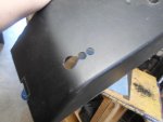
Still workin' on the arm rests.
After establishing the rough slots I used a router with a 1" round grinding bit that's mounted thru a hole in a board mounted that I usually use to clean up pipe notches, to clean up our slots.
Next, I fitted the arm rests in place.
Yup, that should work.
Now gotta make up some mounting/support brackets.
I used some 3/16" x 1" steel I had in the bucket.
I need them to go up 6" from the inside frame rail, across 7" & then down 7" to the outside frame rail.
Popped my bender in the vise & bent them up real quick like.
I will probably weld them in place but just used sheet metal screws to temporarily attach them for now.
I will also need to weld the hand control lever mounts to the frame rails because they keep workin' loose, mainly when braking, & I cant apply much pressure with the nut & bolt because I don't want to collapse the frame rail.
Installed the key switch conveniently near the right hand control but, out of the way.
Oh, ya, here is the end of my test drive.
https://www.youtube.com/watch?v=TCzH-m-mEgQ&feature=em-upload_owner
Attachments
-
 SAM_3299.jpg265.7 KB · Views: 1
 -
 SAM_3296.jpg274.5 KB · Views: 1
 -
 SAM_3295.jpg267.3 KB · Views: 1
 -
 SAM_3292.jpg247.8 KB · Views: 1
 -
 SAM_3305.jpg338.1 KB · Views: 3
 -
 SAM_3302.jpg370 KB · Views: 2
 -
 SAM_3304.jpg282.8 KB · Views: 1
 -
 SAM_3303.jpg322.5 KB · Views: 1
")
- Status
- Not open for further replies.