2017 - Hero (Zero Turn Go Kart)

Status
Not open for further replies.

Functional Artist

Well-known member
Messages
4,411
Reaction score
1,694
Location
Toledo, Ohio
Hero

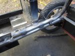
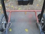
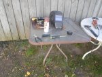
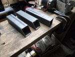
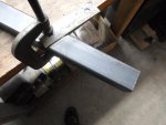
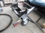
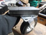
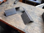
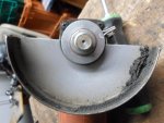
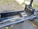
I used the cut off wheel to remove the tabs off of the sides of the scooter & ground off the welds off using a rough wheel on the grinder, before clamping the main frame & the scooters together.

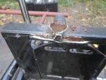
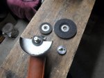
* I finally changed the wheel on the grinder.
Sure got my monies worth out of the old one.
Even had to scrape out debris to fit new wheel on.

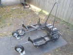
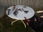
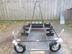
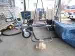
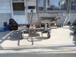
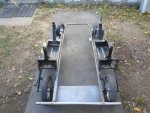
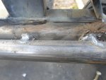
After double & triple checkin' everything from (height all (4) corners), levelness & clearance (ground, wheels etc.), I marked the welding points & took it all apart to clean up the welding points.

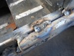
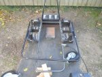
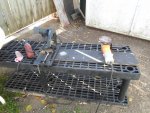
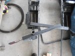
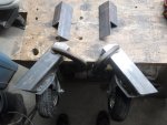
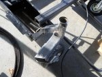
After using a sanding disc on the grinder, I cleaned everything up & re assembled the main frame & scooters & then tac welded it together.

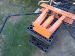
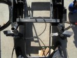
I doubled checked everything again then welded it up good. :thumbsup:
https://www.youtube.com/watch?v=-C3flzyweCg&t=22s&spfreload=10
 

Attachments

  • SAM_2144.jpg
    SAM_2144.jpg
    455.7 KB · Views: 3
  • SAM_2147.jpg
    SAM_2147.jpg
    248.8 KB · Views: 3
  • SAM_2150.jpg
    SAM_2150.jpg
    244.1 KB · Views: 3
  • SAM_2140.jpg
    SAM_2140.jpg
    232.7 KB · Views: 4
  • SAM_2146.jpg
    SAM_2146.jpg
    440 KB · Views: 4
Last edited:

Functional Artist

Well-known member
Messages
4,411
Reaction score
1,694
Location
Toledo, Ohio
Hero

I want the driver to sit pretty much between the rear wheels, to aid our steering concept.

To accomplish this, we need to attach the roll bar/seat back, as far back as possible.

So, We'll start at the battery box.

The frame rails support the sides of our battery box, the rear bumper is the rear & we'll use a piece of small angle across the front.

I primed the battery box & frame area where it mounts to seal it up, because once I weld in the front brace, the battery box will be locked in.

After welding in the front battery brace, I clamped the roll bar into place, making sure there was clearance to remove the batteries.

Then, I welded it in place also. :thumbsup:

https://www.youtube.com/watch?v=f5B0AL-OSsE&feature=em-upload_owner
 

Attachments

  • SAM_2151.jpg
    SAM_2151.jpg
    430 KB · Views: 6
  • SAM_2169.jpg
    SAM_2169.jpg
    327 KB · Views: 4
  • SAM_2167.jpg
    SAM_2167.jpg
    289.3 KB · Views: 4
  • SAM_2157.jpg
    SAM_2157.jpg
    364.9 KB · Views: 3
  • SAM_2156.jpg
    SAM_2156.jpg
    307.2 KB · Views: 4
Last edited:

Functional Artist

Well-known member
Messages
4,411
Reaction score
1,694
Location
Toledo, Ohio
Hero

She's kinda, starting to look like a go kart! :2guns:

I cut off the seat towers & cleaned up the rear arm rest support area.

That will clear the way to help figure the configuration, placement & mounting of our upper frame section.

Our upper frame section will accomplish several tasks.

First, it will begin at & be part of our arm rest.

...then, extend up to where the casters will mount,

...then curve (@~ a 90 degree angle) to go across the front where it will also be the foot rest (since we won't have any foot pedals)

...then curve again where the other caster will mount & finally go back to the other arm rest. :thumbsup:
 

Attachments

  • SAM_2176.jpg
    SAM_2176.jpg
    545.5 KB · Views: 3
  • SAM_2159.jpg
    SAM_2159.jpg
    286.5 KB · Views: 3
  • SAM_2188.jpg
    SAM_2188.jpg
    454 KB · Views: 5

Functional Artist

Well-known member
Messages
4,411
Reaction score
1,694
Location
Toledo, Ohio
Hero

Takin' advantage of this beautiful 70 degree mid November day in NW Ohio & doin' this build in the back yard. :2guns:

That was yesterday, today its like 35 degrees, rainy & windy. :ack2:

Next, I made the upper frame section.

Doing rough measurements, it looks like we are gonna need about 32" from each arm rest mount to the front bends & then about 30" across.

(32' + 30" + 32" = 94")

So, we'll start by cutting our piece of pipe @ 8' which should leave a little extra in case I'm a little off.

I marked our piece of pipe in the center to begin with then, I measured & marked 16" each way from the center to leave a little extra for the bends.

Usually it takes about 50 pumps will produce ~a 90 degree angle.

So, I started with 45 pumps on each side (a little under 90 degrees) for fitting purposes. (It's easier to put it back in the bender & bend it a bit more than try to lessen a bend)

First fitting, it was around 4" too wide.

Put it back in the bender and added 5 more pumps to each side.

Even with both sides @ 90 degrees, on second fitting, it was now about 2" wide.

Still a bit wide so, we'll have to remove a couple of inches from the middle.

After removing 2", I used a piece of angle iron to help line up the (2) pieces for welding.

Yup, that's better! :2guns:

Clamped casters on makin' sure they have ample clearance.

Still gotta add some braces but, this is how the basic frame will look.

https://www.youtube.com/watch?v=RDLB3EMfy14
 

Attachments

  • SAM_2176.jpg
    SAM_2176.jpg
    545.5 KB · Views: 4
  • SAM_2175.jpg
    SAM_2175.jpg
    460.7 KB · Views: 3
  • SAM_2174.jpg
    SAM_2174.jpg
    305.2 KB · Views: 3
  • SAM_2173.jpg
    SAM_2173.jpg
    447.2 KB · Views: 4
  • SAM_2197.jpg
    SAM_2197.jpg
    460.6 KB · Views: 8
  • SAM_2184.jpg
    SAM_2184.jpg
    501.5 KB · Views: 3
Last edited:

Functional Artist

Well-known member
Messages
4,411
Reaction score
1,694
Location
Toledo, Ohio
Hero

I DON'T LIKE THE UPPER FRAME!

It's too wide!

Too boxy!

Front wheels are too far forward!


It makes me feel like a pirate with a steering wheel down below. :ack2:
 

Attachments

  • SAM_2197.jpg
    SAM_2197.jpg
    460.6 KB · Views: 4

chancer

ɔ ɥ ɐ u ɔ ǝ ɹ
Messages
9,358
Reaction score
8
Location
COMFORT, TEXAS
But it has to be that wide for the casters to spin.

I do agree though. Right now it looks long and wide, Like one of those flatbed shopping karts a warehouse store.

Got any ideas?
 

Functional Artist

Well-known member
Messages
4,411
Reaction score
1,694
Location
Toledo, Ohio
Hero

It's drivin' me nuts! :lolgoku:


I don't like it one bit!

Maybe, somehow

...mount casters off scooter's steering goose necks?

...smaller casters?

...gotta stay pneumatic

I'm a look around a bit,

contemplate the situation.
 

Jfive

New member
Messages
645
Reaction score
0
Location
Great falls Montana
Maybe zero turn mower front spindles. There is a Dixon mower I just took the drive hubs and sprockets off at the scrap yard and pretty sure the front wheels and spindles are still there.
 

Functional Artist

Well-known member
Messages
4,411
Reaction score
1,694
Location
Toledo, Ohio
Hero

Maybe zero turn mower front spindles. There is a Dixon mower I just took the drive hubs and sprockets off at the scrap yard and pretty sure the front wheels and spindles are still there.


Yup! :thumbsup: Good idea!

I checked out a couple of zero turn mowers at a local shop.

Wheels are about the same as what i got.

I figured I could use the same concept just do it DIY style.

I did a mock up by hand & measured it out.

Seemed like we had about a 2" difference from where we needed the castor & the scooter goose neck.

Picked up a couple of feet of 2" x 2" square tubing.

I cut our castor mounts on a bit of an angle.

Looks pretty good, I think we can work with that. :2guns:
 

Attachments

  • SAM_2235.jpg
    SAM_2235.jpg
    261.9 KB · Views: 5
  • SAM_2234.jpg
    SAM_2234.jpg
    211.1 KB · Views: 5
  • SAM_2231.jpg
    SAM_2231.jpg
    344.6 KB · Views: 5
  • SAM_2230.jpg
    SAM_2230.jpg
    340.6 KB · Views: 4
  • SAM_2229.jpg
    SAM_2229.jpg
    325.6 KB · Views: 3

Functional Artist

Well-known member
Messages
4,411
Reaction score
1,694
Location
Toledo, Ohio
Hero

I have been thinkin' about our hand controls.

To control this kart without a steering wheel or pedals we will need to be able to accelerate & apply the brakes individually.

That way we can use acceleration and/or braking action to control the kart.

My first idea was to have a handle sticking up thru the arm rest with a grip on it & a standard brake lever off a scooter.

So, the idea was that if the driver pushes both handles forward the kart would go straight forward.

If only, let's say, the left handle was pushed forward, the kart would turn toward the right. ...and the same with the right.

While cruisin', you can use the brakes to turn or a combination of both. :2guns:
 

Attachments

  • SAM_1952.jpg
    SAM_1952.jpg
    184.5 KB · Views: 2

chancer

ɔ ɥ ɐ u ɔ ǝ ɹ
Messages
9,358
Reaction score
8
Location
COMFORT, TEXAS
I dont know how complicated it is or if you need a reversable motor,but I was thinking...

When I used to drive electric Forklifts, they suggested just reversing the Direction rather than braking.
Called "Plugging"
 

OzFab

New member
Messages
15,615
Reaction score
8
Location
Warwick Qld, Australia
Another idea, to eliminate the brake lever, would be to extend the handle beyond the pivot point & attach the brake cable there so, push to go, pull to stop...
 

chancer

ɔ ɥ ɐ u ɔ ǝ ɹ
Messages
9,358
Reaction score
8
Location
COMFORT, TEXAS
Another idea, to eliminate the brake lever, would be to extend the handle beyond the pivot point & attach the brake cable there so, push to go, pull to stop...

Cool idea. Same concept as the Joystick type Forklift controls.
Push forward -pull Reverse
 

Functional Artist

Well-known member
Messages
4,411
Reaction score
1,694
Location
Toledo, Ohio
I dont know how complicated it is or if you need a reversable motor,but I was thinking...

When I used to drive electric Forklifts, they suggested just reversing the Direction rather than braking.
Called "Plugging"

I think most PM motors are reversible.

Seems like it would be hard on the motor.

What was the reasoning behind that concept?
 

Functional Artist

Well-known member
Messages
4,411
Reaction score
1,694
Location
Toledo, Ohio
From the Forklift Company "Crown Lift Trucks"
It was not at all hard on the Motors... but saved the brakes.

Kool! Very informative.

Never heard of "plugging"

Thanks! :thumbsup:

Info may come in handy for future builds.

I kinda like this concept, already got ideas for another build.


I don't think it will work in this situation, though.

The drive wheels off the scooters that I am using are of the "free wheel" style. (spins freely backwards)

For coast ability, I guess.
 

Functional Artist

Well-known member
Messages
4,411
Reaction score
1,694
Location
Toledo, Ohio
Hero

I have another idea...

Seems like it would be simpler... to operate and/or control.

Springs would keep the lever/handle in the center (neutral/coast)

Push the handle forward to accelerate.

Release to coast (spring back to center)

Pull back to apply the brake.

Ya, I think I like this idea better.

I'm a see if I got all the stuff to make it work. :2guns:
 

Attachments

  • SAM_2228.jpg
    SAM_2228.jpg
    251.7 KB · Views: 7
  • SAM_2225.jpg
    SAM_2225.jpg
    208.9 KB · Views: 5
  • SAM_2223.jpg
    SAM_2223.jpg
    243.1 KB · Views: 5
  • SAM_1953.jpg
    SAM_1953.jpg
    171.9 KB · Views: 4

Functional Artist

Well-known member
Messages
4,411
Reaction score
1,694
Location
Toledo, Ohio
Hero

I removed the hideous upper frame.

Got the castor mounts & triangulation braces cleaned up & welded in place.

Ya, I like that a bit better! :thumbsup:

It shortened up the wheelbase (which should aid our steering concept) & now, it don't look so boxy. :2guns:

https://www.youtube.com/watch?v=mCab9OZQI9s
 

Attachments

  • SAM_2241.jpg
    SAM_2241.jpg
    262.4 KB · Views: 5
  • SAM_2245.jpg
    SAM_2245.jpg
    315.3 KB · Views: 5
  • SAM_2254.jpg
    SAM_2254.jpg
    240 KB · Views: 3
  • SAM_2260.jpg
    SAM_2260.jpg
    447.6 KB · Views: 5
  • SAM_2261.jpg
    SAM_2261.jpg
    431.8 KB · Views: 5
  • SAM_2265.jpg
    SAM_2265.jpg
    405 KB · Views: 5
Status
Not open for further replies.
Top