2016 - Beer Crate Racer (winner)

Status
Not open for further replies.

chancer

ɔ ɥ ɐ u ɔ ǝ ɹ
Messages
9,358
Reaction score
93
Location
COMFORT, TEXAS
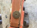
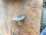
I Then sanded the entire part smooth with a belt sander
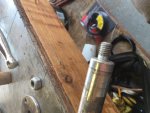
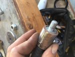
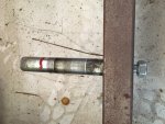
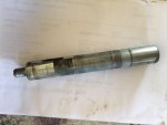
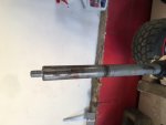
My steering column is one of the 20mm Axles from the Razor Electric karts
The axles have a threaded end, this is an extra axle. The other is on my Krate currently
I found a piece of round stock that fit it nicely.
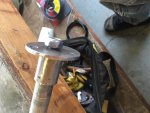
I then used the center hole left from the hole saw, and a nut to line everything up centered nicely then welded.
Then I popped it off.
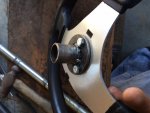
This piece will be permanently welded to my actual steering column.
and the Wheel can be bolted on with the three bolts.
My steering column will have the threaded end cut off flush.
Just needs paint!
Custom DIY, not store bought, no fancy lathe, or machine shop, or lazer cut pieces :thumbsup:
 

Attachments

  • IMG_2553.JPG
    IMG_2553.JPG
    140.9 KB · Views: 14
  • IMG_2554.JPG
    IMG_2554.JPG
    105.2 KB · Views: 13
  • IMG_2555.JPG
    IMG_2555.JPG
    95.2 KB · Views: 13
  • IMG_2557.JPG
    IMG_2557.JPG
    105.8 KB · Views: 13
  • IMG_2558.JPG
    IMG_2558.JPG
    159.1 KB · Views: 14
  • IMG_2559.JPG
    IMG_2559.JPG
    94.4 KB · Views: 18

chancer

ɔ ɥ ɐ u ɔ ǝ ɹ
Messages
9,358
Reaction score
93
Location
COMFORT, TEXAS
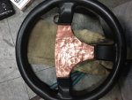
I did not buy the fancy Chrome steering wheel cap either.
Almost looks like a leather wrap, with an airbag!
 

Attachments

  • IMG_2565.jpg
    IMG_2565.jpg
    359.6 KB · Views: 13

chancer

ɔ ɥ ɐ u ɔ ǝ ɹ
Messages
9,358
Reaction score
93
Location
COMFORT, TEXAS
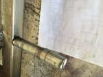
I Finally did a little more work on this thing today. I made some foot pegs. You may recall the steering shaft is an old Razor Buggy Axle. I had another so I cut the ends off and used them for pegs.
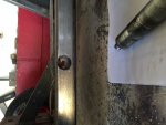
They have a threaded bolt sticking out so I drilled all the way through the frame and the whole peg goes through the frame but only the bolt sticks out the back. I will weld the outside all the way around and the bolt on the inside. There is really no reason for the threads. This should be WAY stronger than just welding them right to the frame. These are solid and so way heavier than needed, but they are the perfect size to slip a 7/8 copper sleeve onto.
 

Attachments

  • IMG_2696.JPG
    IMG_2696.JPG
    114.5 KB · Views: 11
  • IMG_2695.JPG
    IMG_2695.JPG
    134.5 KB · Views: 13
  • IMG_2694.JPG
    IMG_2694.JPG
    99.7 KB · Views: 13
  • IMG_2693.JPG
    IMG_2693.JPG
    77.4 KB · Views: 13
  • IMG_2692.JPG
    IMG_2692.JPG
    58.3 KB · Views: 12
  • IMG_2697.JPG
    IMG_2697.JPG
    142.4 KB · Views: 15

chancer

ɔ ɥ ɐ u ɔ ǝ ɹ
Messages
9,358
Reaction score
93
Location
COMFORT, TEXAS
Also welded the steering wheel mount I made last week to the steering shaft.
Really I just need to order my clutch, and Build a Gas tank.
I made one gas tank, but it was waaaay too big. I gotta find some 3" copper pipe. I can find it on ebay by the foot but It is too expensive.
 

chancer

ɔ ɥ ɐ u ɔ ǝ ɹ
Messages
9,358
Reaction score
93
Location
COMFORT, TEXAS
I have been working on my Brake linkage.
I will utilize a foot brake like on a Mini bike.
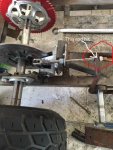
Since the foot pegs were part of an axle I was able to use a bearing to have the pedal rotate on and the back of the linkage pulls the rod when the pedal is depressed. I think this will fit through the slats when I put the krate on.
Still need to clean it up a bit but the fabrication is complete.
Thanks for lookin.
 

Attachments

  • IMG_2697.JPG
    IMG_2697.JPG
    142.4 KB · Views: 23
  • IMG_2282.JPG
    IMG_2282.JPG
    131.2 KB · Views: 21
  • IMG_1890.JPG
    IMG_1890.JPG
    109.8 KB · Views: 22
  • IMG_2741.JPG
    IMG_2741.JPG
    122.6 KB · Views: 23
  • IMG_2740.JPG
    IMG_2740.JPG
    155.8 KB · Views: 30
  • IMG_2739.JPG
    IMG_2739.JPG
    171.5 KB · Views: 26

chancer

ɔ ɥ ɐ u ɔ ǝ ɹ
Messages
9,358
Reaction score
93
Location
COMFORT, TEXAS
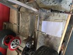
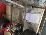
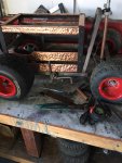
So I liked the design of that brake, Here are some more Pics of how it fit into the Krate slats. All ok.
Problem is it stuck in too far and hit the Recoil starter on the engine.

I am currently bending another linkage rod with a Zig Zag in it.
(no Joe not that kinda Zig Zag)
 

Attachments

  • IMG_2743.JPG
    IMG_2743.JPG
    129.9 KB · Views: 18
  • IMG_2744.JPG
    IMG_2744.JPG
    152.2 KB · Views: 20

chancer

ɔ ɥ ɐ u ɔ ǝ ɹ
Messages
9,358
Reaction score
93
Location
COMFORT, TEXAS
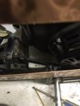
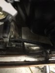
Well I remade the linkage, Cut the pedal mount side shorter and now everything clears. It is really tight but it clears!
Sorry about the crappy pics but it is a dark shot and a crappy angle.
 

Attachments

  • IMG_2748.JPG
    IMG_2748.JPG
    41.9 KB · Views: 16
  • IMG_2750.JPG
    IMG_2750.JPG
    40.3 KB · Views: 16
  • IMG_2740.JPG
    IMG_2740.JPG
    150.6 KB · Views: 22

chancer

ɔ ɥ ɐ u ɔ ǝ ɹ
Messages
9,358
Reaction score
93
Location
COMFORT, TEXAS
Tomorrow I will share a little more on the DIY parts that went into the linkages. This set up cost me exactly 0 Dollars.:wai:

I think this Kart is turning out to be pretty Cool, and VERY low budget!
 

bob58o

SuckSqueezeBangBlow
Messages
9,646
Reaction score
1,851
Location
Chicago-town USA
So I liked the design of that brake, Here are some more Pics of how it fit into the Krate slats. All ok.
Problem is it stuck in too far and hit the Recoil starter on the engine.

I am currently bending another linkage rod with a Zig Zag in it.
(no Joe not that kinda Zig Zag)

Joe needed the zig zags 5 hours before this post.
 

chancer

ɔ ɥ ɐ u ɔ ǝ ɹ
Messages
9,358
Reaction score
93
Location
COMFORT, TEXAS
I wanted to share a little DIY about how I made my brake linkage and pedal Free.
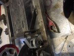
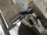
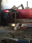
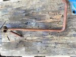
Pic1 This was the steering support that came with my Azuza Kart. I did not use it. I cut off 1 leg and heated and bent 1 more 90° into it. This is the foot pedal and arm in one.
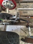
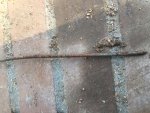
Pic 2 is the 1/4" rod I had laying around, This became the Brake linkage. It was originally off of a Parrot cage. I used a Die to cut 1/4" 20tpi thread into it
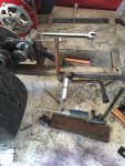
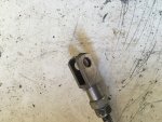
Pic 3 is a piece I also had laying around. The rod threads into it and it attaches to the Brake caliper with a Pin or 1/4" Bolt.
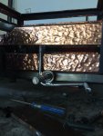
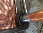
The Final pic is of the 20mm Bearing left over from another cart that the Brake pedal rotates on. It rotates on the 20mm Foot peg that was part of a 20 mm Axle.

Total to build the brake pedal rod and linkages $0. DIY :thumbsup:
 

Attachments

  • IMG_2769.JPG
    IMG_2769.JPG
    189.6 KB · Views: 10
  • IMG_2770.JPG
    IMG_2770.JPG
    165.2 KB · Views: 11
  • IMG_2771.JPG
    IMG_2771.JPG
    145.5 KB · Views: 11
  • IMG_2772.JPG
    IMG_2772.JPG
    104.6 KB · Views: 12

Hellion

Moderator
Messages
8,901
Reaction score
3,917
Can you, uh, zoom out a little on that last pic so we can see the whole assembly? As it stands the photos don't really illustrate what you have devised.

Nevermind--you went retro there describing how to do something you already did.

I have it here in writing that your labor (like the parts) costs nothing. I will keep that in mind should I ever require your services.


chancer

ɔ ɥ ɐ u ɔ ǝ ɹ
Messages
9,358
Reaction score
93
Location
COMFORT, TEXAS
I never would of thought of welding to the bearings themselves. Curious to how they hold up.

I guess I skipped that part, and hard to tell in the pics.
I cut a 3/8" long piece of pipe that the bearing Presses into. The pipe is welded to the Rod.
I would not weld to a bearing, or weld to any metal that still has bearings in it.
 
Status
Not open for further replies.
Top