Sequoia Electrathon Racer

Master Hack

Well-known member
Messages
1,982
Reaction score
3,173
Location
Mountain top Labratory
Let me know it this is a workable solution.
I trimmed the length of the hub to 3 7/8 (3.875)
In the exploded view you will notice the inboard bearing is flush and there are "spacers" between the bracket and rotor.
The outboard bearing is recessed .100 and needs another .200 to leave ya with enough threads.
Shouldn't make any difference where the outboard bearing is.
the wheel flange is moved .125 inboard.
With these changes the clearance of the rotor/bracket interface has been resolved.
The flange remains at .500 from the inboard hub edge.
Please submit this revision to your design board and if approved sign off on it and submit to our engineering staff for implementation.

T308A15CF-786F-4FF6-881D-61BB7926C0A2.jpeg

DBBC10DC-EEC3-4DF2-B504-F49302D482C0.jpeg
 

Master Hack

Well-known member
Messages
1,982
Reaction score
3,173
Location
Mountain top Labratory
Revision 1A is ready for review.
The outside features have all the dimensions called out in your drawing + er - .010
The bearing pockets have not been bored out yet. The rotor side will be flush while the wheel side will be recessed in order to expose enough threads. Egor will make it so enough threads are exposed for a nut and pin. doesn't really matter where toe out board bearing ends up.
The wrong flange is just for demonstration purposes
IMG_3953.jpeg
 

Functional Artist

Well-known member
Messages
4,411
Reaction score
1,694
Location
Toledo, Ohio
That looks Bad Azz :2guns:
...& very professional :thumbsup:

Will it still be ~3 1/4" from the outer "face" of the rotor flange to outer "face" of the wheel flange?
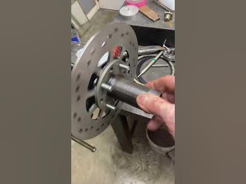
 

Master Hack

Well-known member
Messages
1,982
Reaction score
3,173
Location
Mountain top Labratory
Egor didn't get much done today. The Naughtagator was sent up from the skunkworks for initial review and testing. More on that later.
The flange got welded to the hub, the hub was semi assembled for another runout test. The welding did cause the flange to pull. the runout has increased to about .010. That will get fixed in the spinna thing, later.
Progress so far:

 
Last edited:

Master Hack

Well-known member
Messages
1,982
Reaction score
3,173
Location
Mountain top Labratory
In an effort to correct the runout in the rotor, Egor used the spark spinna thing in the corner. The result is improvement of .007.
Good'nuff.

153FE0A5-ABB3-40A4-81EB-1F33B3C46C5B_1_105_c.jpg

Today was our monthly quality control meeting. There has been too much of the "good'nuff" attitude around here.
So we invited an Asian quality Control consulting firm to improve our methods.
They have a Strict Q/C program there and offered many good tips.
Below is a pic of a typical material review board meeting.

mev-10584762.jpeg
 

Functional Artist

Well-known member
Messages
4,411
Reaction score
1,694
Location
Toledo, Ohio
The rear hub needs
...a wheel flange
...a rotor flange
...& a sprocket flange

3-flange hub
SAM_1578 (1).JPG
.,..or maybe a 2-flange hub (with dual purpose rotor/sprocket flange)
SAM_1577 (1).JPG
Here are a couple of swing arm ideas too
SAM_1580 (1).JPG
 

Master Hack

Well-known member
Messages
1,982
Reaction score
3,173
Location
Mountain top Labratory
I forwarded your blue prints downstairs to the Skunkworks for review by the engineering dept.
Recommendations are as follows:
Drawing 2 is easier to build and keep things straight and concentric.
There is a lot going on there and the spindle should be supported at both ends. A spindle supported on one end is possible with enough gussets extending outboard of the swing arm, and a strong enough spindle. More info as to weight and horsepwer needed.
Why does the drawing show wheel studs with left hand threads? :rolleyes:
 

Functional Artist

Well-known member
Messages
4,411
Reaction score
1,694
Location
Toledo, Ohio
Why does the drawing show wheel studs with left hand threads?
Hey T,
It's a drawing of the left side hub :p

Ima thinkin we gonna need to use a split sprocket
...ta be able to mount a sprocket, to the inside "face" of the rotor flange

Maybe something like this?

#35-54T ($15.95)
https://www.bmikarts.com/35-Split-Sprocket_p_1413.html
or
It may be easier, to work with more of a "blank slate"
...& use something like this?

#35-50T ($44.50)
https://www.bmikarts.com/Azusa-TNT-TUF-N-TRU-Mini-Sprockets-160-Aluminum-35-Chain_p_4006.html

Wadda you think? :unsure:
 

Master Hack

Well-known member
Messages
1,982
Reaction score
3,173
Location
Mountain top Labratory
Drawing #2 (2 flange hub) would be mo bedder. I did, errrahhh, I mean Egor something similar on the blue scrap pile rear axle:

IMG_3994.jpeg


It is keyed to the axle and removable as one piece.
The problem is it requires a big solid piece of material. A piece with an OD bigger than the bolt pattern in the sprocket/rotor and an ID small enough to fit the axle. The sprocket and the rotor will have different bolt patterns, the ID of the split sprocket makes that even mo badder.
The upside is, it's a solid piece, and can be re drilled if necessary. Use a one piece steel sprocket and ya have a hub that can handle a LS swap.
Options, options....
 

Master Hack

Well-known member
Messages
1,982
Reaction score
3,173
Location
Mountain top Labratory
The weekend shift here at the mountain top machine shop discovered a design error in the original drawings.

The engineers from Skunkworks got involved and came up with a solution.

The problem:
The outboard bearing is recessed into the hub and secured with a ny-lock nut. The rules require a safety pin of some sort to prevent a loose nut.
The clearance is such that a pin can not be inserted into the spindle, without bending it. Everyone knows the joys of trying to re used a bent cotter key.
A meeting of the MRB (material review board) was called to find a proper solution, After many hours of deliberation a solution was decided upon.

The following pics might make it easier to understand the problem and solution.

IMG_3995.JPG IMG_3997.JPG
 
Top