Sequoia Electrathon Racer

Functional Artist

Well-known member
Messages
5,630
Reaction score
3,266
Location
Toledo, Ohio
Man, that's really coming together awesome! Looking forward to future progress. :cheers2:
Hey Grizz,

Yup!, she's finally coming together, Thanks! :thumbsup:

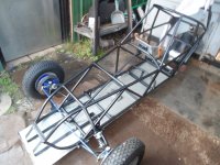
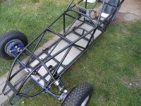
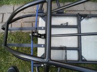
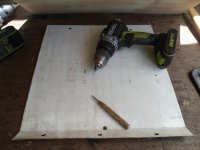
I aligned, drilled (SS= not easy-had ta use some spit-lube)
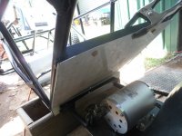
...& then, bolted (will use 12 of them 1/4" x 1/2" Round head Allen's) the floorboard in place
SAM_2453 (1).JPG
Then, marked 'er for trimming

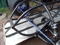
I'm thinkin' about that front "area" as like a "crumple zone"
...or impact absorber
...that will "crumple up" (hopefully, in the event of a light ta medium crash) without damaging the chassis, steering linkage &/or front suspension

So, I only want the floorboard to extend a little bit past the front gussets/bolting points (which will also be used for securing the body panels)
SAM_2456 (1).JPG
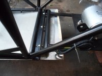
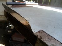
In the rear, I'm thinkin' about curving the floorboard upwards
...ta help direct fresh-cool air into the motor
...& speed controller compartment (ta help keep 'em kool while racing) :2guns:
SAM_2454 (1).JPG
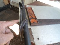
After trimmin', I used a piece of 1" steel bar ta help install a curve, in the rear
SAM_2458 (1).JPG
Like this
SAM_2460 (1).JPG
Re-installed ta double-check the fitment :cornut:
SAM_2470 (1).JPG
Up in front
SAM_2471 (1).JPG
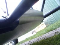
...& back in the rear (under view)
SAM_2473 (1).JPG
 

Functional Artist

Well-known member
Messages
5,630
Reaction score
3,266
Location
Toledo, Ohio
Safety (fire) Wall

I'm going to install a metal safety wall in between the motor/speed controller compartment & the driver

The idea is to help protect the driver in the event of a catastrophic motor failure (shrapnel)
...or electrical issues from motor/speed controller &/or connections
...&/or chain failure

This safety wall will be secured in place, at the top, by the seatbelt shoulder strap bolts
SAM_2530 (1).JPG
...& at the bottom, by the swing arm mount bolts
SAM_2529 (1).JPG
 

Functional Artist

Well-known member
Messages
5,630
Reaction score
3,266
Location
Toledo, Ohio
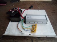
Ima gonna mount the speed controller to the safety wall
SAM_2535 (1).JPG
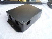
...& was thinkin' that it would probably be best to put them connections "in a box" ;)
SAM_2550 (2).JPG
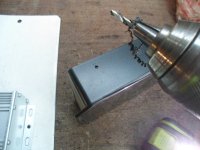
Marked where we need ta put a hole
...ta be able ta insert the wires/connectors
SAM_2551 (2).JPG
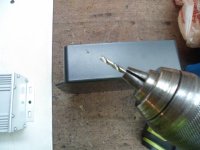
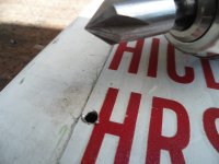
Then, drilled a "pilot hole"
SAM_2552 (2).JPG
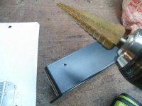
Then, used a "Step drill bit" ta drill a ~7/8" hole
SAM_2553 (2).JPG
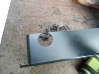
Like this
SAM_2554 (2).JPG
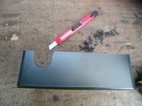
Then, trimmed 'er up
...& rounded them corners a bit :cheers2:
SAM_2555 (2).JPG
 

Functional Artist

Well-known member
Messages
5,630
Reaction score
3,266
Location
Toledo, Ohio
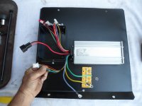
The speed controller, motor "power wires" connection block & signal wires connection box will all be mounted to the safety wall
...so, we gotta drill some holes

Tip1:
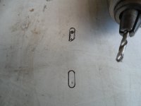
After marking, use a spring-loaded center punch
SAM_2531 (1).JPG
...to "make a dimple" that will help keep the drill bit "in place"
...& not "wondering around"
SAM_2532 (1).JPG
Tip 2:
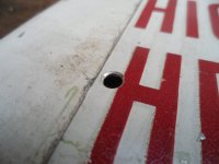
After drilling a hole
...if there are any sharp burrs
SAM_2538 (1).JPG
Use a reamer ta "clean 'em up" :2guns:
SAM_2540 (1).JPG
 

Functional Artist

Well-known member
Messages
5,630
Reaction score
3,266
Location
Toledo, Ohio
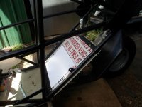
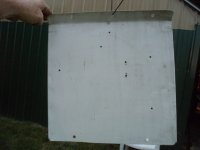
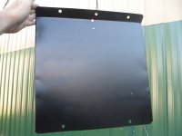
After some smoothin', roundin' & clean up, I gave the safety wall a quick coat of paint
...ta make 'er look nice
...& ta "hide" the fact that it "was" an old sign ;)

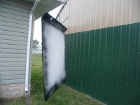
Hung for paintin'
SAM_2557 (2).JPG
Painted the stuff ya don't really see much first (the edges, holes & in all of the nooks-n-crannies)
SAM_2559 (2).JPG
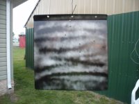
Then, give all of the broad/flat surfaces a light coat

* The first "coat" isn't really an actual "coat"
...but, just a quick drying, light misting

Its purpose is mainly to just get some material (paint) on the surface
...so, the next coat(s) have something familiar (same stuff) & grippy (semi-wet paint) to stick to
SAM_2561 (1).JPG
* Somehow I didn't take any pics of the "finished product" :mad2:
...so, "more to come"! :cheers2:
 

Functional Artist

Well-known member
Messages
5,630
Reaction score
3,266
Location
Toledo, Ohio
Safety wall, painted
SAM_2568 (1).JPG
I added a couple of more wiring "ports" to the connection box
SAM_2572 (1).JPG
...& started working on the wiring
SAM_2570 (1).JPG
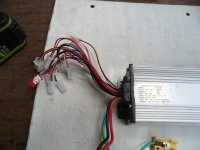
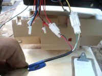
All of the smaller wires/connectors (at the top) are for control & signal circuits (On/Off switch, Reverse switch, Throttle control etc.)

The thicker Red & Black wires (kinda in the middle) are the main power input wires (where ya connect the battery)

The 5-wire connector (I'm holding) is the for the motor's Hall sensors (rotor position signals)

The 3 thick wires (at the bottom) are the motors power wires (sends "power" to the motor)
...& they have their own thermally insulated, connector block (yellow)

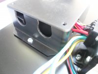
So, most of the wires from the SC enter, the box, thru the side port (except the motors Hall sensor & power wires)
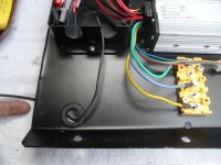
...& then, the wires will exit thru these bottom ports
SAM_2574 (1).JPG
...& go to thru a rubber gromet, in the safety wall, to their individual components :thumbsup:
SAM_2578 (1).JPG
 

Functional Artist

Well-known member
Messages
5,630
Reaction score
3,266
Location
Toledo, Ohio
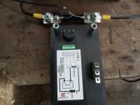
Workin' on some of the wiring, like for instance, the PZEM-051 power meter :thumbsup:
SAM_2352 (1).JPG
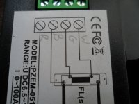
Red wire (not shown) will be for the Positive (+) connection/input for the battery pack (+)
...& to "power" the meter itself

Black wire is for the Negative (-) connection (-)

Green wire is for Battery Negative input (B-)

White wire is for the "power side" Negative input (P-)

All "Blowed up" for old timers eyes :thumbsup:
SAM_2353 (1).JPG
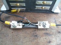
The Shunt (sends info to the power meter)
SAM_2351 (1).JPG
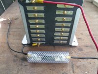
Shunt with insulator/protective cover
SAM_2354 (1).JPG
Battery pack with protective cover
SAM_2357 (1).JPG
Dang it:mad2:
...now, I ain't got any pics of the finished battery pack (with the XT-90 connector) :furious2:
 

Functional Artist

Well-known member
Messages
5,630
Reaction score
3,266
Location
Toledo, Ohio
Battery pack w/XT-90 connector & power meter connection(s)
SAM_2645 (1).JPG
Moving on to the "signal" circuits
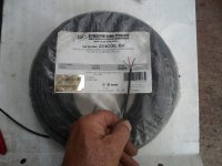
I'm using some of this 22/4 wire (which is 4 individually insulated copper wires, in a common jacket) for the "signal" circuits & the power meter
SAM_2547 (1).JPG
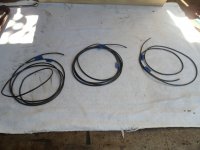
I will use (3) 4-wire "harnesses" to connect the steering wheel(s) switches & meter :thumbsup:
SAM_2579 (1).JPG
Ta help keep 'em "in order" I labeled 1,2 & 3
#1 will connect the On/Off switch & the Reverse switch (both use 2-wire switches)
#2 will connect tie 3-speed switch (requires 3 wires so, 1 wire won't be used)
#3 will connect the power meter (requires 4 wires)

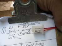
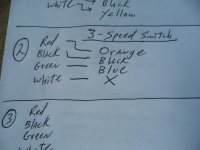
Since the wire colors will "jump around" (or not match up) I'm making notes as to the wire color changes
Like this:
SAM_2583 (1).JPG
...& this
SAM_2592 (1).JPG
More notes ;)
SAM_2594 (1).JPG
 

Functional Artist

Well-known member
Messages
5,630
Reaction score
3,266
Location
Toledo, Ohio
WTF? I'm lost now....

Hey T,

It seems complicated
...but, it's really not

That's kinda why I "blabber" so much, about this stuff
...ta try-n-show the young'ns (& old'ens) it ain't that hard :cheers2:

Ya just gotta "break" everything down into (simpler) individual sections ;)

Let's take (for example) the On/Off circuit:

Up in the c*ckpit on the dash (or in this case on the steering wheel) ya have a simple (2) pole switch (like a Toggle or Key switch)
...then, ya need a "harness" which (in this circuit) is (2) individual wires (1) to connect to each pole on the On/Off switch
...& then, that "harness" "runs" back to the "Electric Lock" plug on the speed controller

* Keep in mind that on (1) end of the "harness" you will need to install the appropriate terminals
...to be able to connect to the terminals on the On/Off switch
&
Then, on the other end, a "female" Molex connector
...to mate with/connect with the "male" Molex connector on the SC
Just do this "over & over" for each individual circuit :sifone:
 

Master Hack

Well-known member
Messages
4,293
Reaction score
6,890
Location
Mountain top Labratory
It seems complicated
Cuz it is!
I get it, its purdy much plug and play.
as long as all components are compatible, voltage and amperage bla bla bla.
l never was able to figure out the smoke release ratings. The smoke containment pressure release valve would open within a few minutes and leave me in a cloud of toxic smoke!
 

Functional Artist

Well-known member
Messages
5,630
Reaction score
3,266
Location
Toledo, Ohio
Circuit Breaker
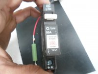
To help protect the entire electrical system we have & are gonna use a 150VDC 50A circuit breaker
SAM_2607 (1).JPG
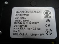
Spec label
SAM_2606 (1).JPG
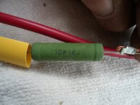
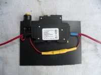
It will also have a pre-charge circuit/feature (momentary switch & big 10W 1Kj resistor)
SAM_2609 (1).JPG
Its purpose is to be able to pre-charge (slowly fill up with energy) the capacitators in the speed controller
...before the main power is turned on
...so, the capacitators in the SC don't have to "deal with" a huge inrush of energy (when the system is first energized)
SAM_2610 (1).JPG
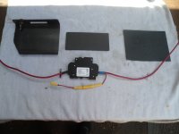
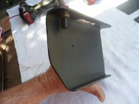
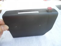
Gonna have ta make a box ta mount everything into

Yup, more TV plastic ;)
SAM_2616 (1).JPG
Had ta do some shapin'
SAM_2619.JPG
...& some whittlin'
SAM_2618 (1).JPG
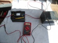
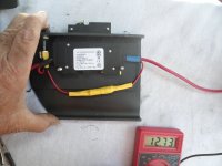
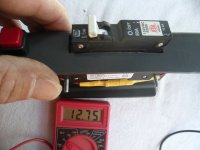
Next, I tested it with a 12V SLA battery (had ta make sure it worked) :thumbsup:

With the CB in the "off" position
...& before engaging the pre-charge switch there is no power/voltage present
SAM_2621 (1).JPG
Push the button & the voltage slowly rises to full battery voltage
SAM_2623 (1).JPG
Then, when ya switch the CB "on"
...the capacitators are already "safely" filled up (or pre-charged)
...& we have the full power of the battery pack available :2guns:
SAM_2625 (1).JPG
 

Functional Artist

Well-known member
Messages
5,630
Reaction score
3,266
Location
Toledo, Ohio
That's cool. It's alien-speak to me, but it's still cool.
Hey Ez,

Back in 2016, when I first joined DIYGK, I didn't even know how to use a multi-meter :huh:
...but, my buddy Sid helped me, tremendously, to gain an understanding of this stuff :cornut:

I'm actually kinda surprised he "put up with my ignorance" as long as he did
...but, TBH I probably wouldn't know or understand 1/2 of the stuff, that I think I know, without him :2guns:

He was a "beast" of an instructor :thumbsup:

I miss him...a lot
...& hope he's doin' well :cheers2:
 

Grizzlymi

Wolverine
Messages
1,359
Reaction score
1,115
Location
Michigan
Hey Ez,

Back in 2016, when I first joined DIYGK, I didn't even know how to use a multi-meter :huh:
...but, my buddy Sid helped me, tremendously, to gain an understanding of this stuff :cornut:

I'm actually kinda surprised he "put up with my ignorance" as long as he did
...but, TBH I probably wouldn't know or understand 1/2 of the stuff, that I think I know, without him :2guns:

He was a "beast" of an instructor :thumbsup:

I miss him...a lot
...& hope he's doin' well :cheers2:


What ever happened to Sid? He was a wealth of knowledge!!
 
Top