Polaris

Functional Artist

Well-known member
Messages
5,654
Reaction score
3,293
Location
Toledo, Ohio
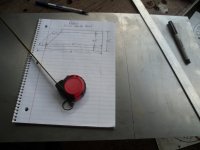
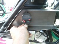
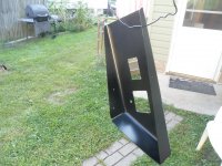
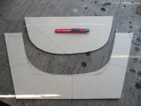
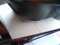
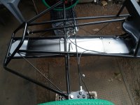
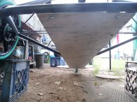
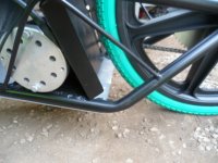
To make up a panel to mount the Circuit Breaker, I came up with a plan
SAM_0638.JPG
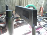
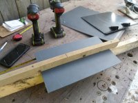
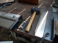
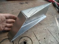
Rounded up some steel, marked it, cut it & then, bent 'er up
SAM_0645.JPG
Kinda like this
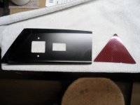
...& then the CB goes about there
SAM_0647.JPG
I tried to make 'er kinda aerodynamic
SAM_0649.JPG
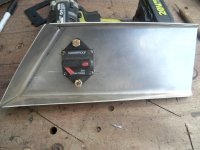
CB dry fit
SAM_0652.JPG
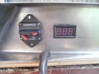
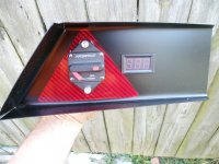
Ima gonna install a voltage meter, right next to the CB
SAM_0656.JPG
Then, cleaned 'er up & sealed 'er up
SAM_0658.JPG
 

Functional Artist

Well-known member
Messages
5,654
Reaction score
3,293
Location
Toledo, Ohio
Here is another excerpt from the Electrathon America (official) Rule Book (page 9) :thumbsup:

12 ELECTRICAL SYSTEM
1. A fuse or circuit breaker is required in any electrical circuit between the battery and any electrical device.
2. All fuses or circuit breakers should be mounted as close as practically possible to the source of power.
3. All fuses or breakers should be sized to protect the wiring to which they are connected. The current rating of fuses and breakers shall be no more than those listed in the adjacent table for standard automotive cable.

13 ISOLATION SWITCH
1. An isolation switch (kill switch) is required on all vehicles.
This switch must have a break current rating that exceeds the maximum current draw of the vehicle.
2. The switch must be located in the main positive power cable between the battery and any motor controller.
3. An actuator may be attached to the switch for remote operation provided that it is durable and reliable.
4. Means must be provided for both the driver and race officials to actuate an isolation switch.
5. The driver must be able to actuate the switch while in driving position and without reaching outside the vehicle.
6. Race officials must be able to actuate the switch from outside the vehicle without reaching in.
7. Two switches may be installed if necessary.
8. A circuit breaker may be used as the isolation switch.
9. The switch or actuator accessible from outside the vehicle must be mounted within a solid red triangle whose sides are at least 4 inches and in contrast to vehicle color or graphics.
10. Wiring must be well insulated and securely attached to the frame or body. All wiring must be kept free from moving parts and protected from chafing.
11. Wiring that passes through a hole with sharp edges or through sheet metal must be protected by an insulating grommet or other suitable device.
12. Terminals must be secured so they will not come loose or short out during a competition.
13. No part of the electrical system may use the vehicle frame as a conductor. The frame must not be grounded.


So, the CB will serve a re-settable fuse & Isolation Switch (to comply with #1 & allowed by #8)

To comply with # 9, I rounded up a scrap piece of red vinyl (left over from the mini-Jeep)
...& cut it into a ~4" triangle ;)

SAM_0665.JPG
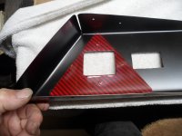
Then, installed it just under, where the CB mounts :cheers2:
SAM_0666.JPG
Wrapped 'er around the backside to kinda act as a gasket, for the CB
SAM_0667.JPG
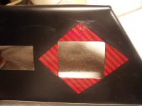
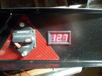
Then, mounted the CB & Meter in place
...& did a quick 12V test :sifone:

* The meter will be wired so, it will be "on", when the CB is "on"
...& the system is "powered up" or "live"
...& displaying the systems current voltage level 🤓
SAM_0670.JPG
Ready for installation :banana:
SAM_0694 (2).JPG
 

Master Hack

Well-known member
Messages
4,330
Reaction score
6,985
Location
Mountain top Labratory
It is a great ride (journey) and a great ride! I’m impressed with what you can do with just a few basic hand tools! I’m still skeptical….


YOUNGSTERS! Listen up! You can do it. Use your brain, figure it out! Jump in and do it, then do it again if ya have to. Sometimes l make a part 2-3 times before l like it.
Here is an example of what can be done.

then there is the rocket kart moron
 

Functional Artist

Well-known member
Messages
5,654
Reaction score
3,293
Location
Toledo, Ohio
It is a great ride (journey) and a great ride! I’m impressed with what you can do with just a few basic hand tools! I’m still skeptical….


YOUNGSTERS! Listen up! You can do it. Use your brain, figure it out! Jump in and do it, then do it again if ya have to. Sometimes l make a part 2-3 times before l like it.
Here is an example of what can be done.

then there is the rocket kart moron
Thank you sir! :cheers2:
...skeptical? :huh:

I enjoy designing & building every one of my creations
...& every creation "is" a journey
...& am glad you guys are coming along with me, for these journeys :thumbsup:

I think of my karts almost like paintings or sculptures
...where ya come up with a rough idea
...& "run with it"

Plus, ya can ride on/in my creations
...where as ya can't ride on a painting or a sculpture (well I guess ya could...Um...never mind...wiredo) 🤪

Yup, "Nuthin' to it but, ta do it" :2guns:
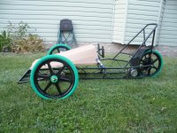
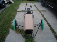
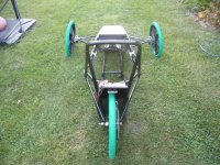
...& (drum roll) I'd like to announce that "we officially have a roller" :bannana::sifone:

Side view
SAM_0729 (2).JPG
A view from the front
SAM_0738 (2).JPG
A view from the rear
SAM_0731 (2).JPG
* Also, if ya didn't notice, I'ma doin' some test fittin' of a CAD hood too ;)
 

Functional Artist

Well-known member
Messages
5,654
Reaction score
3,293
Location
Toledo, Ohio
More details

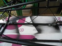
Here is the throttle & linkage set up
SAM_0719 (2).JPG
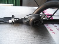
It's just a simple thumb throttle, with a couple of small holes added (the second hole is for a return spring)
SAM_0722 (2).JPG
Actuated by the throttle pedal via a short cable
SAM_0720 (2).JPG
 

Functional Artist

Well-known member
Messages
5,654
Reaction score
3,293
Location
Toledo, Ohio
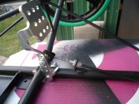
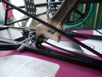
The brake pedal didn't have enough "travel" :mad2:
...so, I had to move the dual brake cable connector up (1) hole (to get more "travel" or a longer "throw") :cheers2:

But then, the cable mounting bracket was "aimed" at the lower hole :huh::furious2:
...so, I had ta do some adjustin'

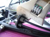
I used my handy brake cable mount adjustin' tool (totally just made that name up) :p
...ta adjust 'em
SAM_0711 (2).JPG
Just position it over the mounting tab
...adjust 'er down fairly tight
...& then, start adjustin' :thumbsup:

* It even has a built in "scale" for use on/with all of the different thickness(es) of brake cable mountin' tabs 🤪
SAM_0712 (2).JPG
 

Functional Artist

Well-known member
Messages
5,654
Reaction score
3,293
Location
Toledo, Ohio
The CAD cowl is looking good.
Thank you sir!

Did ya happen to notice the plastic dashboard up under there? :unsure:

SAM_0710 (2).JPG
How did I make it you ask? :smartass:

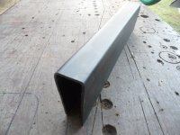
A piece of black plastic (from the back of an old projection TV)
...clamped to the narrow end of a 1" x 3" board (with another board) :thumbsup:
SAM_0700 (2).JPG
Used a heat gun ta soften 'er up
...& then, kinda "wrapped" it around the board
SAM_0702 (2).JPG
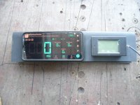
This kinda what I have in mind

The dashboard will just have a PZEM-051 Power Meter, which displays the Batt Pack Voltage
...the system current Wattage & Amperage
...& also, records the Watt Hours used
& also,
A cell phone with a speedometer app, that besides showing the current speed (with a big 'ol number)
...it will also, track & record the max speed
...the avg speed
...& the distance traveled (more on this later) ;)
SAM_0706 (2).JPG
 

Functional Artist

Well-known member
Messages
5,654
Reaction score
3,293
Location
Toledo, Ohio
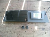
Um...where is the On/Off switch? :unsure:
You are gonna have an On/Off switch...right? :popcorn:

Holy Crap, I forgot to include an On/Off switch, on the dashboard :mad2:

Well, let's see if we can squeeze on in there :thumbsup:
SAM_0739 (2).JPG
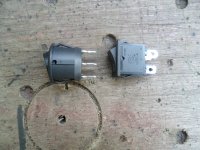
I'ma gonna go with the round one
...'cause a round hole is way easier ta drill, than a square one :cornut:
SAM_0741 (2).JPG
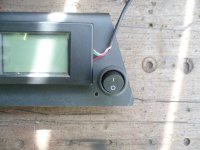
Looks like it'll fit about right here
...& easily accessible for a right-handed driver :cool:
SAM_0743 (2).JPG
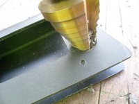
A Step Drill Bit "walked" right thru that plastic
SAM_0747 (2).JPG
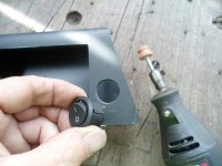
Then, cleaned 'er up a bit, for a custom fit, with the Dremel
SAM_0749 (2).JPG
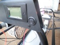
...& Wa-la :sifone:
SAM_0798 (2).JPG
 
Top