Polaris

Master Hack

Well-known member
Messages
4,330
Reaction score
6,985
Location
Mountain top Labratory
That looks great! Yer looking for just a snug fit on the bearings. Then use either loctite 648, 660, or 680. One of those should be multi purpose enough to use on yer other applications as well.

Being cheap and a hack ( bad combination) l use whatever l have. The red stuff is purdy tenacious but can be less permanant wiith heat, if you find it has to come apart.
 
Last edited:

Functional Artist

Well-known member
Messages
5,654
Reaction score
3,293
Location
Toledo, Ohio
That looks great! Yer looking for just a snug fit on the bearings. Then use either loctite 648, 660, or 680. One of those should be multi purpose enough to use on yer other applications as well.

Being cheap and a hack ( bad combination) l use whatever l have. The red stuff is purdy tenacious but can be less permanant wiith heat, if you find it has to come apart.
Kool, thanks! :cheers2:

Looking on E-Bay for 660 or 680 Loctite, I see a bunch of listings for stuff that are past the expiration dates, listed on the bottle. :huh:

I'd think if Loctite Corp. bothered to include an expiration date on the label, they did it for a reason. :thumbsup:

If I already had it I'd probably try & use it
...but, it doesn't seem like a good idea to buy already expired stuff o_O (even for a small discount)
Any thoughts/comments about expired Loctite? :popcorn:
 

Functional Artist

Well-known member
Messages
5,654
Reaction score
3,293
Location
Toledo, Ohio
You're gonna be sorry you asked...

0901d1968065f1f4_pdf_preview_medium.pdf

Bottom line don't tighten the axle nut down on the inner race much more than finger tight, unless there is an accurate length spacer between the two bearings.
Sorry, I'm buggin' the crap out of you today

It's a raining
...so, I can't do much outside today :mad2:

Can you expand on "accurate length spacer between the (2) bearings"?
...like when a spacer would be needed or helpful?
...& why?

Like, for example the bicycle hubs have a built-in ridge (on both sides) that the outer race of the bearing "sits" against
...so, the bearings don't really need a spacer to keep them in place

But,

I'm thinkin' if/when "side loaded", like when the front wheels turn, a spacer would help to "spread the load" across both bearings

Thoughts :popcorn:
 

Master Hack

Well-known member
Messages
4,330
Reaction score
6,985
Location
Mountain top Labratory
Like, for example the bicycle hubs have a built-in ridge (on both sides) that the outer race of the bearing "sits" against
...so, the bearings don't really need a spacer to keep them in place

But,

I'm thinkin' if/when "side loaded", like when the front wheels turn, a spacer would help to "spread the load" across both bearings
The spacer is really just idiot proofing.
If the spacer is the exact length of the distance between the bearings when installed any moron could tighten the axle nut without preloading the bearing. An intellegent being on the other hand could tighten the nut (nylon locknut or castle nut) to the point of removing any free play yet not binding up the bearing with excessive preload.
Then drill and pin it if necessary.
Turning (lateral) forces affect the contact angle inside the bearing, but won’t be helped by the spacer.
The hub, axle and bearings form a relatively rigid assembly with regards to lateral forces.
Assuming all the parts involved have proper clearance to one another.
 

Functional Artist

Well-known member
Messages
5,654
Reaction score
3,293
Location
Toledo, Ohio
Back ta workin' on the spindles :cheers2:

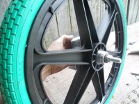
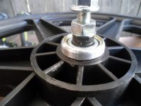
Inside or back side
SAM_0323 (1).JPG
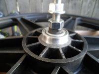
Outside or front side
SAM_0321 (1).JPG
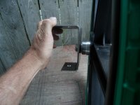
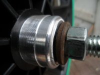
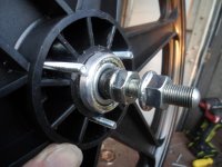
* Notice small inner washer (on both sides) only contacts the inner race
...so, the outer race & hub can rotate freely

The larger outer washer is a bit bigger, to help protect the bearing & seal
...& we still have plenty of shaft still available, to add a "lock pin" ("Safety wire or Cotter pin" as required by the rule book) :thumbsup:
SAM_0322 (1).JPG
 

Functional Artist

Well-known member
Messages
5,654
Reaction score
3,293
Location
Toledo, Ohio
Waitin on the spin test!
looks good!
Thanks! :thumbsup:

We'll get there, I'ma still workin' on mockin' everything up :cheers2:

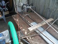
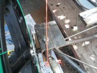
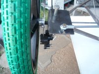
Established the Ackermann angle by "running" a string, tied to the center of the rear axle, up to the King Pin
SAM_0326 (1).JPG
Another view
SAM_0327 (1).JPG
An up'er close'er view ;)
SAM_0328 (2).JPG
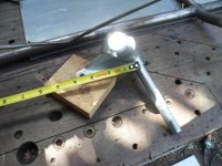
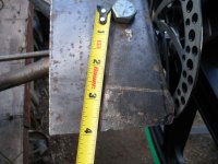
FYI the Spindle Arm length on many standard go kart spindles is ~3 1/2"
SAM_0330 (1).JPG
Since this is kinda experimental & we have lots of material to work with, I'm gonna install (3) holes for attaching the tie rod
...at 2 1/2", 3" & 3 1/2"
...this way we have options to test :)
SAM_0331 (1).JPG
Kinda like this
SAM_0335 (1).JPG
 

Functional Artist

Well-known member
Messages
5,654
Reaction score
3,293
Location
Toledo, Ohio
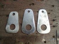
The Pitman arm that I made seems a bit short
...so, I made up longer ones

They are made outta a bit thinner material (~1/16")
...so, I doubled 'em up, ta make a stronger junction ;)
SAM_0333 (1).JPG
Made up some Tie Rods too (5/16" steel rod)
SAM_0337 (1).JPG
Top view
SAM_0338 (1).JPG
Another view
SAM_0336 (1).JPG
 

Functional Artist

Well-known member
Messages
5,654
Reaction score
3,293
Location
Toledo, Ohio
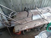
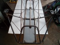
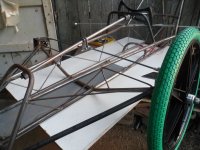
Also, did ya'all notice the full-length Aluminum "Belly Pan", as required by the rule book? (the rear section is not installed, in the pics)
...& chassis gussets that double as "Belly Pan" mounts? :unsure:
 

Functional Artist

Well-known member
Messages
5,654
Reaction score
3,293
Location
Toledo, Ohio
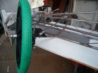
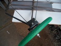
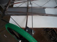
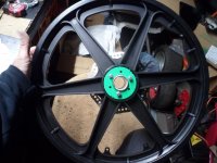
The wheel (with green tire) that I've been using, for these mock ups, is the rear wheel with the threaded hub.

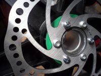
I just threaded the brake rotor adapter onto the threads, of the rim, & bolted the rotor on.

So, I'ma still needin' to install brake rotors onto the front rims
...but, buying a 34mm tap & trying to tap threads, onto the hubs of the front rims didn't seem too promising
...& I'd rather NOT spend $75.00+ at my local machine shop, ta get 'em done
So, Im'a gonna try another idea :idea2:

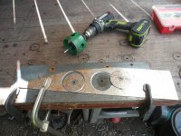
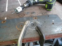
I cut a couple of 3" discs outta some 1/16" steel
SAM_0344.JPG
Then, cut a 1 1/2" hole outta the center (using the same "pilot hole")
SAM_0347.JPG
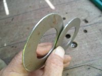
After a bit of clean up, they looked like this
SAM_0349.JPG
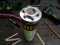
Used an old spray paint can as a "centering jig" to center the brake rotor adapter, with the steel disc
SAM_0350.JPG
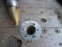
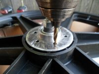
After drillin' the holes for the brake rotor bolts, I had ta ream 'em out a bit more, ta fit on/over the wheel hub
SAM_0354.JPG
On the rim, they look like this
SAM_0355.JPG
Another view
SAM_0356.JPG
 

Functional Artist

Well-known member
Messages
5,654
Reaction score
3,293
Location
Toledo, Ohio
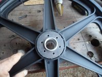
Front rim/hub, unmolested
SAM_0360.JPG
Front rim/hub, after the attack
SAM_0361.JPG
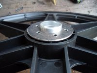
Put (1) of the "hub rings", that I made up, over the hub
...lined every other bolt hole up, in between the structural walls
...& then, drilled (3) 3/16" holes
SAM_0362.JPG
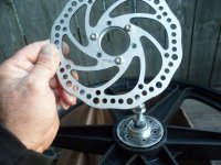
By doin' it this way the rotor will still be bolted (with (3) bolts) to the adapter the "stock" way ;)
SAM_0364.JPG
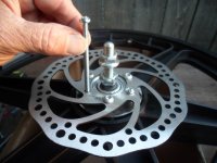
...& have (3) thru bolts running thru the rim
SAM_0365.JPG
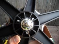
Other side
SAM_0366.JPG
Another angle
SAM_0367.JPG
With another "hub ring" on the outer side, the rotor & adapter shall be attached securely to the rim
...& (hopefully) not affect the strength of the wheel/hub junction too much) :thumbsup:

But wait, there's more...:popcorn:

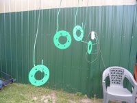
After paintin' the hub rings (& during assembly) I'ma gonna use some of the Loctite (when it gets here)
...ta "glue" the rotor adapter, to the hub

This way, the (3) bolts will supply a mechanical bond
...& the Loctite, will strengthen the junction/joint (maybe even by double) by supplying an adhesive bond :2guns:
...& & & the rotor will still be removable (if ever necessary) :cool:
 
Top