Building a go kart size Aerial Atom

Functional Artist

Well-known member
Messages
4,371
Reaction score
1,636
Location
Toledo, Ohio
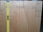
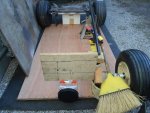
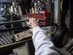
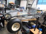
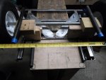
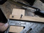
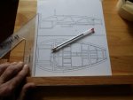
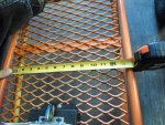
Thinkin' about what Sid said, lets get some foot area measurements.

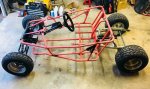
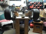
I'll use Desteny's Cotton Candy Kart (it's pretty roomy & comfy) as an example.

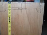
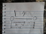
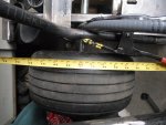
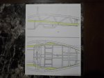
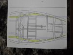
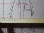
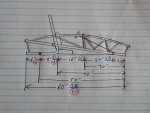
The floor is ~13" wide & as of now I'm thinkin', we want a floor area of ~12 wide.

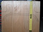
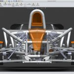
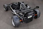
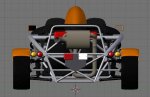
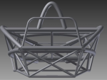
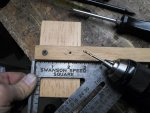
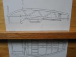
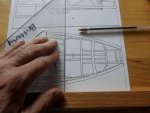
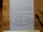
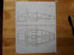
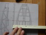
General proportioning, it looks like the nose box on the Atom is around twice as wide as it is tall.

So, if we want a foot area of 12" wide then, the height would need to be ~6".

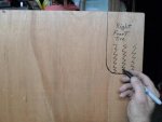
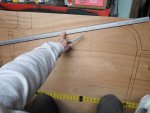
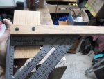
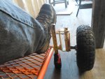
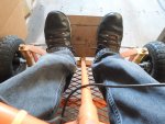
But, when I sat on the kart & measured, it looks like 12" wide is quite adequate for boots & a steering shaft, but @ only 6" high, 1/2 of my boot will stick up/out like Fred on Flintstones. :lolgoku:
Well! :idea2: I guess we'll have to get back to that. :p
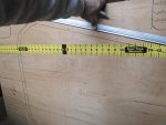
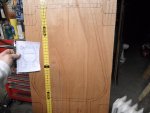
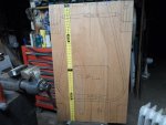
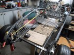
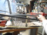
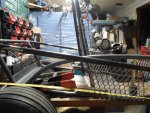
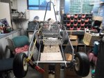
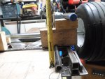
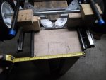
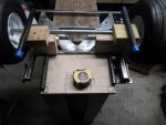
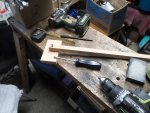
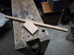
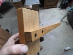
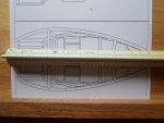
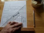
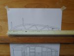
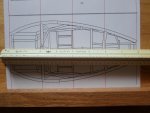
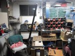
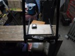
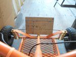
For visual reference, I went ahead & marked a scrap piece of board (6" x 12") & propped at the foot of the kart, this gives us a better idea of what a 6" x 12" (vertical area) looks like (on the kart & with boots)
 

Attachments

  • SAM_2614.jpg
    SAM_2614.jpg
    382 KB · Views: 3
  • SAM_2615.jpg
    SAM_2615.jpg
    302.2 KB · Views: 5
  • SAM_2617.jpg
    SAM_2617.jpg
    284.5 KB · Views: 3
  • SAM_2619.jpg
    SAM_2619.jpg
    310.6 KB · Views: 6

Functional Artist

Well-known member
Messages
4,371
Reaction score
1,636
Location
Toledo, Ohio
Now that we have some rough measurements to work with, lets do some drawing. :thumbsup:

The lower ribbon rail seem like the best place to start.
It's supposed to bow out ward & angle upward from the front to the rear, but it looks to actually sit pretty horizontal, on the kart.
(from the top view & just for proportioning purposes) :cheers2:

So, lets see if we can start there.

First, I marked where the front tires, axle & nose box would be.
(front up)
I flipped the board over for measurin' & markin' where the rear tires & frame rails "kick back" between the tires.
(bottom up)
Turned 'er side ways & drew some nice rounded bends (maxed to the sides of the board)

Then, drew lines to connect the front & rear.
I also marked where the seat would be.

Looks pretty kool! :2guns:

It don't look anything like an Atom :ack2:
...but still looks kool. :lolgoku:

Back to the drawin' board.
Probably gonna have to get another board.
:idea2: maybe try a longer board too (~30" x 60")
 

Attachments

  • SAM_2629.jpg
    SAM_2629.jpg
    265.3 KB · Views: 4
  • SAM_2627.jpg
    SAM_2627.jpg
    256.7 KB · Views: 4
  • SAM_2625.jpg
    SAM_2625.jpg
    212.7 KB · Views: 4
  • SAM_2622.jpg
    SAM_2622.jpg
    449.9 KB · Views: 4
  • SAM_2621.jpg
    SAM_2621.jpg
    334.4 KB · Views: 4
  • SAM_2631.jpg
    SAM_2631.jpg
    261.2 KB · Views: 4
  • SAM_2633.jpg
    SAM_2633.jpg
    264.4 KB · Views: 4
  • SAM_2635.jpg
    SAM_2635.jpg
    238.9 KB · Views: 4
  • SAM_2638.jpg
    SAM_2638.jpg
    240.8 KB · Views: 5
  • SAM_2639.jpg
    SAM_2639.jpg
    260.6 KB · Views: 4

Functional Artist

Well-known member
Messages
4,371
Reaction score
1,636
Location
Toledo, Ohio
Yup, I think we can do this! :cheers2:

I've been studding this thing some more & also been doin' some figurin' & drawin' :idea2:

Looking at the first pic, from the top view an Atom kinda looks to have a simple/standard go kart shape.

Imagine just (1) seat & it sitting a little further back than the (2) seats are now.
If we have (lets say) a 48" wheelbase & the seat back starts ~8" from the rear, there would still be ~40" to the front axle/foot rest area.
This should leave plenty of leg & foot room & then, even if we add ~6" ahead & behind the wheels, we'll end up with an overall length of ~60". (just gotta figure out that toes stickin' out thing) :ack2:


Lookin' deeper, examining the overall shape of the super structure (sounds kool to say) I keep sayin' to myself, "WOW! this thing is Bad Azz"

IMO
It's more like a 4D structure. (if there is such a thing)
It has width & height & depth, but with these "bows" on angles it takes on like a 4th dimension. :2guns:
This frame even seems to "flip". :smiley_omg:
Look at the (2) different views of the same (black) car. (pics 5 & 6)
In the first one, it looks like the top rail curves down to intersect with the bottom rail. (like it actually does)
In the second pic it looks like the top rail is pretty much straight & the bottom rail curves up to intersect with it. (looks kinda kool, but not reality)

* Comparing the front view of the Atom & the Arrow.
They have some similarities, but the level of engineering between the (2) seems to be quite a bit different.
 

Attachments

  • 6807461436552541934.jpg
    6807461436552541934.jpg
    50.3 KB · Views: 2
  • SAM_2565.jpg
    SAM_2565.jpg
    301.5 KB · Views: 2
  • SAM_2566.jpg
    SAM_2566.jpg
    246.1 KB · Views: 2
  • Aerial Atom top view.png
    Aerial Atom top view.png
    83.8 KB · Views: 2
  • 2012-ariel-atom-700-ddmworks-3.jpg
    2012-ariel-atom-700-ddmworks-3.jpg
    209.5 KB · Views: 4
  • 2014_ariel%20atom_atom__01.jpg
    2014_ariel%20atom_atom__01.jpg
    603.9 KB · Views: 3
  • Arrow 150 front view.png
    Arrow 150 front view.png
    87.1 KB · Views: 105

Joe-405

Enjoying New Projects
Messages
2,673
Reaction score
69
Location
U.S.A.
I could give you the measurements off my spiderbox if you need them. It’s really comfortable for 2 adults with poly racing seats.

And actually is pretty close to the design of the atom.
 

Attachments

  • 05D40245-AA1C-4176-9D92-996D3F54837B.jpeg
    05D40245-AA1C-4176-9D92-996D3F54837B.jpeg
    160.8 KB · Views: 10

Functional Artist

Well-known member
Messages
4,371
Reaction score
1,636
Location
Toledo, Ohio
I brought the Damien kart inside & partially reassembled 'er to use as a model to play with Atom some dimensions & stuff. :thumbsup:

This frame has more Atom like characteristics than I realized. :cheers2:

I (temporarily) moved the rear axle all the way back on the Damien kart. (for measurement purposes)

Measurin', if I add an imaginary 6" to the rear & ~4" to the front, we would have ~48" wheelbase with a ~54" overall frame length. :2guns:

I then, propped the rear of the frame up on an angle, to mimic the angle of the lower "rib rail".

We can use the bench top to represent the floor of the cockpit & a piece of 1" tube to represent the bowed "top rib" rail.

Next, I clamped one end of the tube to the left front of the frame & curved/bowed it back & down to just behind the rear axle.

Yup, kinda startin' to resemble an Atom :wai:
 

Attachments

  • SAM_2729.jpg
    SAM_2729.jpg
    333.3 KB · Views: 6
  • SAM_2726.jpg
    SAM_2726.jpg
    284.9 KB · Views: 4
  • SAM_2725.jpg
    SAM_2725.jpg
    320 KB · Views: 3
  • SAM_2724.jpg
    SAM_2724.jpg
    354.5 KB · Views: 4
  • SAM_2723.jpg
    SAM_2723.jpg
    357.1 KB · Views: 5
  • SAM_2731.jpg
    SAM_2731.jpg
    342.5 KB · Views: 6
  • SAM_2733.jpg
    SAM_2733.jpg
    270.6 KB · Views: 5

Tpdingo

Member
Messages
903
Reaction score
1
Location
Bellmore, NY
Yup, kinda startin' to resemble an Atom :wai:

No it doesnt. Its way too big and completely the wrong shape. Atoms look like this:


:roflol:

Yes it is starting to take the shape of an atom, but any framed 4-wheel machine with wire-frame sidewalls will kind of resemble and atom to some degree for that matter.
 

Functional Artist

Well-known member
Messages
4,371
Reaction score
1,636
Location
Toledo, Ohio
I think were makin' progress

A 4" - 5" length frame seems do able :thumbsup:

Now, lets look at it & try to lock down some measurements from a different direction, width.
:idea2:
If we work with/use a standard 36" rear axle, we should have ~22" - 24" of available space in between the tires.

Let's say, the upper "ribbon rails" are ~24" apart, at their highest & widest point. (that seems to put 'em right above the inside edge of the rear tires)

The lower "ribbon rail" end tubes (the ones with the blue caps) could be ~16" apart
(that would leave ~3" - 4" from each rail/pipe to the tire)
The lower motor compartment box) tubes could then be ~12" apart.

The motor compartment box should be ~5" off of the ground & then there would be ~6" to the "ribbon rail".

* Pay no attention to the square tubes. They are just holding the axle.

Yup, kinda close :2guns:
 

Attachments

  • c3a9679788ad44da67cd6026350a7a8b.jpg
    c3a9679788ad44da67cd6026350a7a8b.jpg
    32.6 KB · Views: 2
  • SAM_2774.jpg
    SAM_2774.jpg
    244.5 KB · Views: 2
  • SAM_2773.jpg
    SAM_2773.jpg
    217.8 KB · Views: 3
  • SAM_2772.jpg
    SAM_2772.jpg
    232.3 KB · Views: 2
  • SAM_2771.jpg
    SAM_2771.jpg
    298.7 KB · Views: 2
  • SAM_2770.jpg
    SAM_2770.jpg
    234.9 KB · Views: 2
  • untitled.png
    untitled.png
    177 KB · Views: 2

Functional Artist

Well-known member
Messages
4,371
Reaction score
1,636
Location
Toledo, Ohio
Still workin' & studying on the frame, old school style :thumbsup:

I printed a couple of copies of a nice-n-clean blueprint type drawing of the frame that I found on Google.

But, I didn't double check the framing & some got cut off :ack2:

We can work with these for a minute :cheers2:

I used a yellow highlighter to "highlight" the lower "rib rails".

I also used blue ink to visually "bring up" the straight part of the rear of the lower "rib rail" tube.
(to help show the correlation of it's width to the nose box's dimensions & help judge them curves)
...but, we got no nose box? :lolgoku:

Still helps a bit, till I get some complete copies :2guns:
 

Attachments

  • SAM_2834.jpg
    SAM_2834.jpg
    222.9 KB · Views: 3
  • SAM_2835.jpg
    SAM_2835.jpg
    239.5 KB · Views: 5

Functional Artist

Well-known member
Messages
4,371
Reaction score
1,636
Location
Toledo, Ohio
I got some better (complete) copies of the frame diagram. :thumbsup:

I looked everywhere but, I can't find my drawin' "T" square.

I have other squares but, not a "clean" one. :ack2:

I'ma gonna have ta make one.

Just, square up a couple of pieces of oak scraps & screw 'em together.

Gotta make sure it's square. (A square ain't worth a crap if it ain't square) :2guns:

Yup, that'll work :cheers2:
 

Attachments

  • SAM_2885.jpg
    SAM_2885.jpg
    288.4 KB · Views: 0
  • SAM_2881.jpg
    SAM_2881.jpg
    240.4 KB · Views: 1
  • SAM_2880.jpg
    SAM_2880.jpg
    274 KB · Views: 2
  • SAM_2877.jpg
    SAM_2877.jpg
    284.9 KB · Views: 2
  • SAM_2875.jpg
    SAM_2875.jpg
    283 KB · Views: 2
  • SAM_2887.jpg
    SAM_2887.jpg
    200.2 KB · Views: 1
  • SAM_2888.jpg
    SAM_2888.jpg
    220.9 KB · Views: 2

Functional Artist

Well-known member
Messages
4,371
Reaction score
1,636
Location
Toledo, Ohio
Lets do some figurin'-n-drawin' :thumbsup:

I rounded up a drawin' board (a smooth surface with a nice straight edge), our "new" "T" square, some maskin' tape & a copy of the frame diagram.

First we gotta "square" it up.
I held the "T" square along the edge of the board, aligned it with a straight line on the copy & taped the corners down, to hold it in place.

I sized it so, the frame is pretty close to 8" long in the copy.

Using red ink I marked the left & right ends (at 0" & at 8"), right in the middle (at 4") & then, split each of the sides & marked it. (at 2" & 6")

So, I'm figurin', if the frame is 8" long (in the copy) & we want to make one ~48" long (in real life) then (I think) we can use the rule 2" (on the copy) = 12" (on the kart)

* Our lines even seem to "line up" pretty well with several of the main lines & components on the frame.

This should help us size & judge & align everything nicely. :2guns:
 

Attachments

  • SAM_2890.jpg
    SAM_2890.jpg
    199.7 KB · Views: 1
  • SAM_2891.jpg
    SAM_2891.jpg
    210.4 KB · Views: 1
  • SAM_2892.jpg
    SAM_2892.jpg
    226.7 KB · Views: 1
  • SAM_2897.jpg
    SAM_2897.jpg
    235.8 KB · Views: 2
  • SAM_2896.jpg
    SAM_2896.jpg
    214.8 KB · Views: 1
  • SAM_2895.jpg
    SAM_2895.jpg
    194.8 KB · Views: 2
  • SAM_2894.jpg
    SAM_2894.jpg
    213.2 KB · Views: 0
  • SAM_2893.jpg
    SAM_2893.jpg
    197.7 KB · Views: 1
  • SAM_2898.jpg
    SAM_2898.jpg
    238.9 KB · Views: 2
  • SAM_2899.jpg
    SAM_2899.jpg
    222.4 KB · Views: 4

Functional Artist

Well-known member
Messages
4,371
Reaction score
1,636
Location
Toledo, Ohio
Also did some drawin' to figure the width. :thumbsup:

First, we had to "split this baby" in 1/2, right down the middle.

So, according to the drawin', our kart should be ~24" wide @ the widest point.

The side height seem to be ~12" from the bottom of the motor box to the top of the top "rib rail".

Hmmmm. We may have to tweak those numbers a bit. :cheers2:

I guess we'll just have to see how it works out. :2guns:
 

Attachments

  • SAM_2902.jpg
    SAM_2902.jpg
    251.4 KB · Views: 1
  • SAM_2901.jpg
    SAM_2901.jpg
    253.6 KB · Views: 2
  • SAM_2900.jpg
    SAM_2900.jpg
    245.8 KB · Views: 1

Tpdingo

Member
Messages
903
Reaction score
1
Location
Bellmore, NY
C'mon Functional Artist....you got skill. Figure out how to wave the mouse and keyboard around and put your ideas in the computer.

Trust me...it will be well worth it.

Nice designs though...even if primitive methods were used
 

Functional Artist

Well-known member
Messages
4,371
Reaction score
1,636
Location
Toledo, Ohio
Reminds me of drafting class in high school. Man, that was primitive by today's standards..

Yup, that's where I learned, High School Industrial Arts class back in like 1982. :thumbsup:

---------- Post added at 12:02 PM ---------- Previous post was at 11:50 AM ----------

C'mon Functional Artist....you got skill. Figure out how to wave the mouse and keyboard around and put your ideas in the computer.

Trust me...it will be well worth it.

Nice designs though...even if primitive methods were used

Thanks :cheers2:

Don't worry, I'll look into it. :thumbsup:

As far as I know, designing in CAD is only (1) part of it, figuring out how to accomplish it in "real life" is a whole different situation.

I can design & draw all kinds of kool stuff, but then I have to take into account "is it doable?
..."can I do it real life"?

How do you take the design from the screen & make it real?
…with primitive tools?
 

Kartorbust

Well-known member
Messages
3,896
Reaction score
188
Location
Utica, NE
In the last 30 years when went from pencil and slide rule to sitting behind a keyboard to design everything. Doing it all by hand is a dying art at this point.
 

Tpdingo

Member
Messages
903
Reaction score
1
Location
Bellmore, NY
How do I connect my chop saw, grinder & welder to my computer?

Can you 3D print a full size go kart?
...in steel? :smiley_omg:

Lol my little printer can't print any bigger than 10x9x8" and only in plastic...not to say it can't print some impressive and useful things though.

I know some printers can print metal but not big enough, and not sure show strong...but it's metal.

You can use the Universal Converter box..just make sure to select chop saw and angle grinder option at checkout.

https://xkcd.com/1406/
 

Functional Artist

Well-known member
Messages
4,371
Reaction score
1,636
Location
Toledo, Ohio
Lets bend some pipe :thumbsup:

I think we can incorporate the seatback/rollbar in with the bottom of the motor box.
(see drawing below) :cheers2:
Started with a 10" piece of pipe.
Marked at 20", 60" & then, at 100"
Bent it at the 20" mark to ~75* angle & also at the 100" mark to ~75*
(being sure to keep 'em in alignment)
Then, turned 'er ~90* & bent 'er to the max right in the middle at the 60* mark.

A ratchet strap easily draws 'em together to ~12" apart. :2guns:
 

Attachments

  • SAM_2839.jpg
    SAM_2839.jpg
    340.2 KB · Views: 3
  • SAM_2840.jpg
    SAM_2840.jpg
    352.6 KB · Views: 3
  • SAM_2841.jpg
    SAM_2841.jpg
    319 KB · Views: 3
  • SAM_2842.jpg
    SAM_2842.jpg
    223 KB · Views: 2
  • SAM_2577.jpg
    SAM_2577.jpg
    280.3 KB · Views: 5
Top