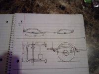
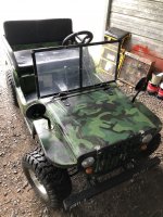
'wittle 'wesistor (Mini Jeep)

Kartorbust

Well-known member
Messages
3,901
Reaction score
194
Location
Utica, NE
fun fact about the roxor or whatever. do you want a brand spanking new 1970’s Jeep cj5?? pull the whole front end/vin tag << hey that’s illegal! and bolt it to the front end of a roxor.. bam new Jeep! sooo many people did this and I think of them as the last jeeps. grandfathered into the world by hacks.
If I recall, Mahindra had the rights to produce these during WW-II and then continued to make them after the war as the Roxor. Pretty much same specs as the old Jeep. But no way am I paying $30K for one brand new.
 

Thepartsguy

Well-known member
Messages
1,145
Reaction score
894
If I recall, Mahindra had the rights to produce these during WW-II and then continued to make them after the war as the Roxor. Pretty much same specs as the old Jeep. But no way am I paying $30K for one brand new.
You can read up about the no give backs ordeal. where people were building brand new cj5’s with nothing more then a vin tag/front clip you could imagine it caused some worry when the buyers were asked to return the Roxors for destruction or somthing. either give back a road legal stunning cj5 or revert the work and give back the roxor. some people I guess fought tooth and nail to hide/keep there cj5’s Edit: did I mention you got to build the good Jeep to not the amc you got the small pre ‘76 front clip so that means you could also have a street legal clone mail Jeep. Or even better a cj5 willys! i Think you could bolt the willys stamped tailgates right on and hang the gate chains no modifications. Of course the hood depending on what year was also stamped willys.
 
Last edited:

Functional Artist

Well-known member
Messages
4,423
Reaction score
1,706
Location
Toledo, Ohio
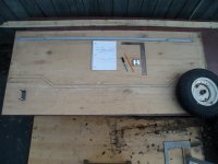
I took the drawings & measurements
...& started attacking a piece of ~1/4" plywood with a ruler, square, a pencil & a sharpie :thumbsup:

First, I started with a 48" wheelbase
...but, it didn't seem right/proportionate (the wheels looked too far apart)
SAM_6104.JPG
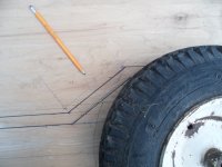
So, I tried the 44.5" WB
...& it looked much better

* One of the "visual markers" I like to maintain is the "look" of the frame, where it curves up a bit, just in front of the rear wheel ;)
SAM_6109.JPG
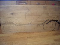
Then, after everything was drawn out
...maybe something like this :2guns:
SAM_6122 (1).JPG
 

madprofessor

"Loose Cannon Creations"
Messages
2,899
Reaction score
889
Location
Jacksonville, Florida
Great scale drawing, looks like the seat is even with the tops of the tires. That should definitely help keep the center of gravity low enough. Is the motor going to sit like cargo in the back, or do you plan on encasing and fan cooling it? I can imagine it would stay just below line of sight with the top of the bed in the back.
 

Functional Artist

Well-known member
Messages
4,423
Reaction score
1,706
Location
Toledo, Ohio
Great scale drawing, looks like the seat is even with the tops of the tires. That should definitely help keep the center of gravity low enough. Is the motor going to sit like cargo in the back, or do you plan on encasing and fan cooling it? I can imagine it would stay just below line of sight with the top of the bed in the back.
Thanks, Mad! :cheers2:

Yup, that's what I was thinkin'
...& the motor will be mounted (out of sight) under the cargo area :thumbsup:

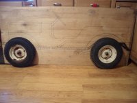
Here is the full size drawing with wheels
SAM_6126 (1).JPG
 

Functional Artist

Well-known member
Messages
4,423
Reaction score
1,706
Location
Toledo, Ohio
Let's talk about the frame & suspension :thumbsup:

Many "replica" or "bodied" go karts use a simple Ladder style frame
...& the body is just a facade (or outer cover)

I'm thinking, since I'm designing & building a frame, from scratch, I'd like to incorporate a few features
...which may even strengthen it as well :2guns:

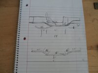
Here is kinda what a "stock" jeep CJ frame looks like (top of pic)
...& below is kinda what I'm thinking for a rear trailing arm

* Notice it would be "curved" to "mimic" the look of a leaf spring :sifone:

It would connect to the frame in front of the rear wheel (like a CJ)
...& use (2) coil-over shocks (1) on each side (not shown)

The rear of the trailing arm would curve upwards a bit
...& then "cross-over" to the other side
...but, would not be connected (to the frame)

The rear axle
...motor
...& brake system would all be mounted on this trailing arm :cheers2:

* Thinking about using this concept for the front axle/suspension too 😉
SAM_6117.JPG
 

Functional Artist

Well-known member
Messages
4,423
Reaction score
1,706
Location
Toledo, Ohio
are you going to try to make the interior look like a willys?
I guess the best answer would be "kinda" :cornut:
...but, they really don't have much of an interior to them

I going to try & have the seats "kinda" where they should be
...with the inner wheel wells right behind the seats
&
The steering wheel will (hopefully) be "kinda" where it should be 😉
...with the "instruments" (speedo & guages) in the center of the dash (like a "big" CJ)
...but, there won't be a transmission "hump" or drive shaft "tunnel" between/under the seats (more foot room) :thumbsup:
 

Functional Artist

Well-known member
Messages
4,423
Reaction score
1,706
Location
Toledo, Ohio
So, thinking about "how" the frame needed to be shaped, first I thought of something like this:

*Notice the "leaf spring looking" trailing arms? :thumbsup:
SAM_6099.JPG

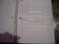
Thinking about it more, I came up with these (3) options: (Notice: these frames are facing the other direction than the above pic)
SAM_6120 (1).JPG

The excessive curves in (A) didn't seem necessary :huh:

The (B) option was simpler design
...but, (as seen in the above (1st) pic) extra bars would be required for mounting the seats 🤔

The (C) option (with its (2) inter-locking pieces) seemed like it would make a stronger frame
...& also, have the seat support "built in" :sifone:

So, I'd have to say Option (3) is the winner :banana:
 

Functional Artist

Well-known member
Messages
4,423
Reaction score
1,706
Location
Toledo, Ohio
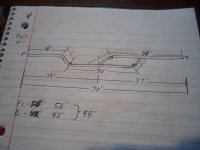
After further evaluation, I revised the frame dimensions just a bit

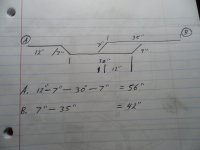
So, for the "main rails" it looks like we need (2) 98" pieces, each cut into
...a 42" piece (for the rear section)
...& a 56" piece (for the front section)
SAM_6124 (1).JPG
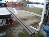
Picked up some pipe
...2 "sticks" of (1/2" Schedule 40) water pipe
SAM_6125 (1).JPG
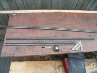
Then, cut the pieces I needed, to the above specifications
SAM_6134 (1).JPG
 

Functional Artist

Well-known member
Messages
4,423
Reaction score
1,706
Location
Toledo, Ohio
Um...how exactly did you get
...56" from 16" + 3" + 30 + 3? (that adds up to ~52" by my calculations)
...& 42" from 36" + 3"? (& that adds up to ~39")

Well, I'm glad you asked :thumbsup:

I kinda forgot but, the distance from the "roller" to the die in the bender is ~4 1/2"
...& I usually just start off with 6" when doing a bend close to the end of a piece
...but & also, for this situation, I wanted to add a bit more (length) to be able to accommodate the battery box, that I plan on mounting under the seat :)

So, it looks like my left brain made the adjustments
...but, my right brain forgot to add them changes, to the diagram 🤔

Here is the revised diagram :cheers2:

The total lengths are the same, I just made some adjustments to the "bend points" ;)

* Notice, I went with 7" for the "up/down" transitions, for just a little bit deeper area for the battery box :cornut:
SAM_6154 (1).JPG
 

madprofessor

"Loose Cannon Creations"
Messages
2,899
Reaction score
889
Location
Jacksonville, Florida
Oww! Unfortunately, my tenderized brain can't hold those many ideas. All I can think is a faux leaf spring on each side, with some concealed actual suspension. Only when being bounced would the truth come out.
That great plywood drawing shows about 3" of travel before the tires hit the fenders, and I'm pretty sure actual Jeeps and Willys had a lot more, albeit with concrete shocks. May I assume there will be a lot of travel in that swingarm?
 

Functional Artist

Well-known member
Messages
4,423
Reaction score
1,706
Location
Toledo, Ohio
Oww! Unfortunately, my tenderized brain can't hold those many ideas. All I can think is a faux leaf spring on each side, with some concealed actual suspension. Only when being bounced would the truth come out.
That great plywood drawing shows about 3" of travel before the tires hit the fenders, and I'm pretty sure actual Jeeps and Willys had a lot more, albeit with concrete shocks. May I assume there will be a lot of travel in that swingarm?
There should be around 2" - 3" of available suspension travel (front & rear)
...but, IMO they probably won't "travel" much more than ~1"

It's not being designed or intended to be a "radical" off-road vehicle

Think more like a parade vehicle, that can go off-road ;)

Speaking of parades, that's (1) of my goals for this kart.
If I can get it done in time, I'd like to see if I can enter my 'wittle 'wesistor in the 2023 Toledo Jeep Fest Parade Aug 24, 2023
https://toledojeepfest.com/

This pic is from the 2019 parade :thumbsup:
Where they are stackin' 'em :2guns:
Jeep Fest 2019.png
 

madprofessor

"Loose Cannon Creations"
Messages
2,899
Reaction score
889
Location
Jacksonville, Florida
Okay, 4-wheelers with more money than sense, and less concern for their rides. Go for it, build extreme, those folks won't be impressed with less.
 

Functional Artist

Well-known member
Messages
4,423
Reaction score
1,706
Location
Toledo, Ohio
Okay, 4-wheelers with more money than sense, and less concern for their rides. Go for it, build extreme, those folks won't be impressed with less.
They do it 'cause they can :devil2:
...they are "kinda made" to do that :thumbsup:
...& nothing usually gets damaged :cheers2:

Sorry, didn't mean to "freak" you out :innocent:

* I don't think any other production vehicle, on the entire planet, that can do that :2guns:
** Notice the front axle articulation :smiley_omg:

Here is what the parade actually looks like:
 
Last edited:

Functional Artist

Well-known member
Messages
4,423
Reaction score
1,706
Location
Toledo, Ohio
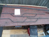
So, I bent both "A" pieces at the 7" mark (25 pumps per bend)
...& then at the 30" mark (25 pumps per bend)
...then, flipped them over & bent them at the other 7" mark (25 pumps per bend) (like in the diagram)

The "B" pieces were simply bent at the 7" mark (also 25 pumps per bend)
...& here is what they look like (so far) :cheers2:
SAM_6138 (1).JPG

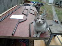
It looks like Ducky approves ;)
SAM_6144 (1).JPG
 

Functional Artist

Well-known member
Messages
4,423
Reaction score
1,706
Location
Toledo, Ohio
I cut the ends off, on angles, where the pieces needed to be welded together
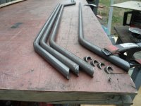
SAM_6161 (1).JPG
...& did some rounding so they would mate up, with the pipe nicely
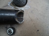
SAM_6167 (1).JPG
Then, took the pieces to the full size drawing, to do a "dry fit"
...so, I could mark where the (2) pieces needed to be aligned, for welding
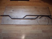
SAM_6172 (1).JPG
Then, cleaned the ends up (for welding)
...& clamped them down, in a jig, to suppress movement (during welding)
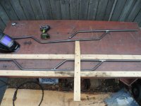
SAM_6187.JPG
Welded them together
...then, flipped the piece over
...clamped it back down
...& welded the other side
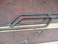
SAM_6195.JPG
Then, did the same to the other (2) pieces
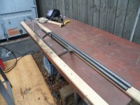
SAM_6197.JPG
* IMO Marking & cutting
...then, marking & bending
...& then, welding both rails simultaneously, seems to make it easier to make them almost identical ;)
 
Top