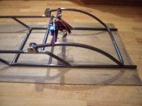
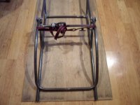
'wittle 'wesistor (Mini Jeep)

Functional Artist

Well-known member
Messages
4,420
Reaction score
1,705
Location
Toledo, Ohio
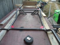
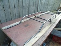
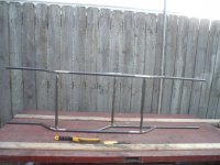
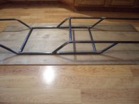
So now, we have (2) 2-dimensional frame rails
...& when we connect them together, with a few cross bars, we'll have a 3-dimensional tubular frame (aka Space Frame)

Where these rails "go" is represented by the dashed line, in this drawing
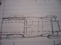
SAM_6199.JPG
This drawing gives a rough idea of the suspension concept that I'm going to try-n-use
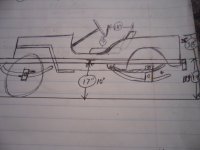
SAM_6200.JPG
I made up a "model" of my faux Leaf Spring Trailing Arm idea (It will help, with the orientation of the curves, for bending)
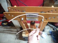
SAM_6235.JPG
The original idea was to use this curved trailing arm idea, for both the front & rear suspensions
...but now, I'm thinking about possibly splitting the front "cradle" into pieces, to allow for some "flexibility"

So, to try this idea, I cut a couple of 24" pieces
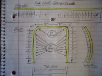
...marked them (as per the bending diagram)
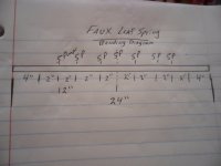
SAM_6224.JPG
I applied (5) pumps at 2" intervals (leaving 4" alone on each end)

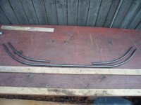
Here is the difference between a bent piece
...& unbent piece
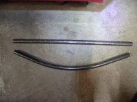
SAM_6219.JPG
 

Functional Artist

Well-known member
Messages
4,420
Reaction score
1,705
Location
Toledo, Ohio
Those (2) "pieces" seemed to come out pretty close to what I had in mind

So, I drew up a bending diagram (for the rear curved trailing arm/cradle)
...cut a piece of pipe
...marked it
...& bent it, as per the diagram :thumbsup:
SAM_6265.JPG
Um...Functional Art (it looks kool & does something too) :sifone:

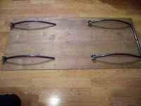
I bent the (faux leaf springs) curves on (2) ends first
SAM_6230.JPG
Then turned the piece 90*
...& bent the "main" bends ;)

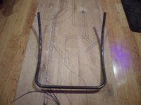
Here is a top view of the rear "cradle"
SAM_6243.JPG
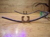
...& here is a side view, with the axle mounts "set" in place :cheers2:
SAM_6247.JPG
 

madprofessor

"Loose Cannon Creations"
Messages
2,899
Reaction score
889
Location
Jacksonville, Florida
Hydraulic Pipe & Tube Bender - 12 Ton (harborfreight.com)

Link above looks like it's what you have, says it's for schedule 40 and 80 pipe. For $150, I'm interested, just don't know schedule ratings for pipes. What wall thickness is 40 and 80? What thickness is standard water pipe from hardware stores like Home Depot? I bend EMT by manual benders, but what says it's for 3/4" says it will also bend 1/2" schedule ___?___ pipe, don't remember. So, how's it go on the sizing?
 

Functional Artist

Well-known member
Messages
4,420
Reaction score
1,705
Location
Toledo, Ohio
Hydraulic Pipe & Tube Bender - 12 Ton (harborfreight.com)

Link above looks like it's what you have, says it's for schedule 40 and 80 pipe. For $150, I'm interested, just don't know schedule ratings for pipes. What wall thickness is 40 and 80? What thickness is standard water pipe from hardware stores like Home Depot? I bend EMT by manual benders, but what says it's for 3/4" says it will also bend 1/2" schedule ___?___ pipe, don't remember. So, how's it go on the sizing?
Hey Madd,

Yup, I have/use a regular old pipe bender.

The pipe I use is standard waterpipe (available from any hardware store)
It's called 1/2" Sch 40
...but, it's really 5/8" ID. x 7/8" OD. with a 1/8" wall

IMO it's good-n-strong
...& easy to work with too

FMU Schedule 80 pipe has thicker walls (probably for high pressure situations)
...& probably too heavy for building go kart frames
...is probably harder to find
...& probably costs more too
 
Last edited:

Functional Artist

Well-known member
Messages
4,420
Reaction score
1,705
Location
Toledo, Ohio
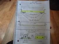
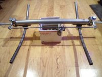
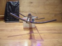
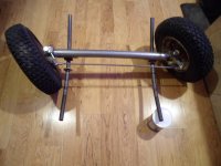
I designed & built a tubular front axle :thumbsup:
As per this diagram
SAM_6269.JPG
Top View
SAM_6367.JPG
Side View (sitting in front of the FS drawing, roughly where it should be mounted, on the Jeep):cheers2:
SAM_6365.JPG
 

madprofessor

"Loose Cannon Creations"
Messages
2,899
Reaction score
889
Location
Jacksonville, Florida
Wondering if you heated up that tube before pounding or squeezing out the ends of it to ovals. Wondering because I've never learned the temps and times for heat treating, and could use some skewl larnin' on dat. I'm always concerned if heating up steel with my welder is hardening the steel, making it brittle, annealing it, etc. The varied results of grinding things down afterwards doesn't tell me a thing.
 

Functional Artist

Well-known member
Messages
4,420
Reaction score
1,705
Location
Toledo, Ohio
Wondering if you heated up that tube before pounding or squeezing out the ends of it to ovals. Wondering because I've never learned the temps and times for heat treating, and could use some skewl larnin' on dat. I'm always concerned if heating up steel with my welder is hardening the steel, making it brittle, annealing it, etc. The varied results of grinding things down afterwards doesn't tell me a thing.
Nope, I never use heat when bending &/or forming steel
 

Functional Artist

Well-known member
Messages
4,420
Reaction score
1,705
Location
Toledo, Ohio
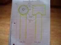
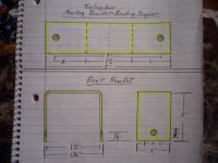
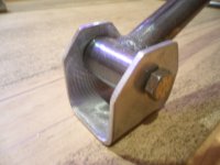
I made up some bushing holders
...& mounting brackets, as per these drawings
SAM_6382.JPG
SAM_6378.JPG
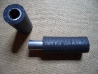
...& made some bushings
SAM_6412.JPG
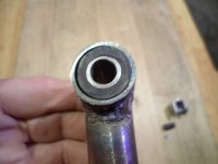
Bushing in Bushing Holder
SAM_6420 (1).JPG
...& then, welded 'em on (aligned with a rod to help give us some nice "hinge action"
SAM_6408.JPG
Then, (after cooling) I assembled the Trailing Arm with Bushing Holder, Bushing & Mounting Bracket
SAM_6423 (1).JPG
Here are the (2) front Trailing Arm(s)
...& rear Trailing Arm assemblies, ready for alignment & welding onto the frame :thumbsup:
SAM_6428 (1).JPG
 

Functional Artist

Well-known member
Messages
4,420
Reaction score
1,705
Location
Toledo, Ohio
Now that we have the front & rear sub-assemblies pretty much done, let's get back to the "main frame"

I wanted to keep the trailing arms "in line" with the frame (same width)
...so, where the front trailing arms mounted, on the axle (how far apart) was kind of the determining factor on how wide the frame should be
...plus, I also had to make sure that the front wheels could turn (stop to stop) without hitting the frame.
SAM_6372.JPG
* My dimension conversion chart indicated that the body width should be ~34" wide
...so, I went with a ~36" wide "track" (standard 36" rear axle)
...& after accounting for wheel turning clearance, it looks like the main frame should be ~20" wide

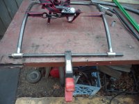
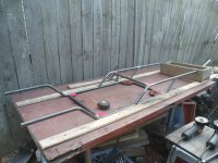
So, I set up a welding jig (just 2 boards, screwed down to the work bench)
..."butted" both frame rails up to the boards
...& then, I could measure how long to make the cross-bars

** I figured (3) cross-bars, strategically placed should "do it" (plus the front & rear bumpers, not shown)
...kinda like this
SAM_6447 (1).JPG
Squared it up real nice (using magnetic squares & also manual squares, in several different directions)
...& then, tac'ed welded 'er all together
SAM_6451 (1).JPG
Flipper 'er over
...put 'er back in the jig
...& did it again
SAM_6454 (1).JPG
Flipper 'er up sideways
...& started welding 'er up good
SAM_6456 (1).JPG
...& now, we have a "main frame" :sifone:
SAM_6458.JPG
Um...I think this would be considered a 3D Space Frame, Denny :cheers2: :innocent: :devil2:
 

madprofessor

"Loose Cannon Creations"
Messages
2,899
Reaction score
889
Location
Jacksonville, Florida
considered a 3D Space Frame
What you have so far is a ladder frame (mehhh) that wants to be a truss frame (super tough). If you'll just splice in some diagonal pieces leaning in the opposite direction from the diagonal parts of the frame (making "V's"), preferably making single point connections from the existing diagonals weld points as opposed to just any old where along the horizontals, you'd have a true truss frame that can't be bent by vertical load or impact. aka: Mama Cass slamming down from a sky-eye wheelie.
 

Functional Artist

Well-known member
Messages
4,420
Reaction score
1,705
Location
Toledo, Ohio
What you have so far is a ladder frame (mehhh) that wants to be a truss frame (super tough). If you'll just splice in some diagonal pieces leaning in the opposite direction from the diagonal parts of the frame (making "V's"), preferably making single point connections from the existing diagonals weld points as opposed to just any old where along the horizontals, you'd have a true truss frame that can't be bent by vertical load or impact. aka: Mama Cass slamming down from a sky-eye wheelie.
Hey MadPro,
Well, if you lay a ladder down horizontally & attach a wheel to each corner then, you would have a Ladder frame
...& "if" you then, jump up & down, in the middle of that frame, it can/will flex!

But, "if" you have (2) side frame rails (upper & lower) intersecting & bracing each other
...& now, "if" you jump up & down, in the middle of this frame, how much do you think it can/will flex?

The tubular mini-Jeep frame that I designed & made seems 3D to me
...but, call it whatever you want, I was just trying to make a good-n-strong frame
...& am trying to keep the weight & complexity to a minimum (yea, right) :innocent:

FYI:
So far, the main frame consists of ~256" (~21') of pipe (~21lbs.) ;)

The rear trailing arm ~70" (~6') of pipe (~6lbs.)
...& front trailing arms ~48" (~4') of pipe (4lbs.)

All totaling ~31' of pipe, which should weigh (~31lbs.) :thumbsup:

* Not including axles, hardware etc.

For anyone interested, here is some info on the subject :cheers2:

Chassis explained

As you design a racing car, it is important that you know the requirements of your engineering work. The nature of the race car's normal operation and fatigue life depend on the structure and material composition of the car. Therefore, topics such as metallurgy and structural design are important for the designer to grasp. The whole concept of engineering considerations is that you keep in mind four aspects, where they are appropriate:

Any good chassis must do several things:
•Be structurally sound in every way over the expected life of the car and beyond. This means that nothing will ever break under normal conditions.
•Maintain the suspension mounting locations so that handling is safe and consistent under high cornering and bump loads. This means that there is no flexing of the body, or at least to reduce flexing on lowest possible value.
•Support the body panels and other components so that evevrything feels solid and has a reliable life span.
•Protect the driver from external intrusion.

Structural stiffness is the basis of what you feel at the seat of your back bottom. It defines how a car handles, body integrity, and the overall feel of the car. Chassis stiffness is what separates a great car to drive from what is merely OK.
Contrary to some explanations, there is no such thing as a chassis that doesn't flex, but some are much stiffer than others. Even highly sophisticated Formula 1 chassis (actually, Formula 1 has monocoque structure) flex, and sometime some limited and controlled flexing is built in the car.
The range of chassis stiffness has varied greatly over the years. Basic chassis designs each have their own strengths and weaknesses. Every chassis is a compromise between weight, component size, complexity, vehicle intent, and ultimately, the cost. And even within a basic design method, strength and stiffness can vary significantly, depending on the details.
There is no such thing as the ultimate method of construction for every car, because each car presents a different set of problems.
Some think an aluminium chassis is the path to the lightest design, but this is not necessarily true. Aluminium is more flexible than steel. In fact, the ratio of stiffness to weight is almost identical to steel, so an aluminium chassis must weigh the same as a steel one to achieve the same stiffness. Aluminium has an advantage only where there are very thin sections where buckling is possible - but that's not generally the case with tubing - only very thin sheet. And even then, aircraft use honeycombed aluminium to prevent buckling. In addition, an aircraft's limitation is not stiffness, but resistance to failure. Aluminium problems are overcomed something with Audi Aluminium Spaceframe (ASF), very expensive and for now made in limited models.

Ladder Chassis (Body on frame technology)

This is the earliest kind of chassis. From the earliest cars until the early 60s, nearly all cars in the world used it as standard. Even in today, most SUVs still employ it. Its construction, indicated by its name, looks like a ladder - two longitudinal rails interconnected by several lateral and cross braces. The longitude members are the main stress member. They deal with the load and also the longitudinal forces caused by acceleration and braking. The lateral and cross members provide resistance to lateral forces and further increase torsional rigidity. Since it is a (little bit more than) 2 dimensional structure, torsional rigidity is very much lower than other chassis, especially when dealing with vertical load or bumps.
This technology you can find today in some basic auto racing categories. Most known is kart. On picture below you can see chassis of an Superkart car without bodywork.


https://www.formula1-dictionary.net/chassis.html
 

Functional Artist

Well-known member
Messages
4,420
Reaction score
1,705
Location
Toledo, Ohio
A space frame is closer related to a Monaco or unibody construction than anything else. Still a ladder frame.
Hey Denny,
Well, I look at it this way.
A piece of waterpipe has 3 dimensions (7/8"t x 7/8"w x however long)
...& when layed on its side, it has a certain "load bearing capacity" (per length)

Then, "if" you stack (2) pieces of pipe, on top of each other (1 3/4"t x 7/8"w x whatever length)
...that "load bearing capacity" increases
...but, "if" they are kept individual, they can't really help each other (no hands)

Now, "if" you were to connect the (2) pieces of pipe together (weld, bolt or clamp) they can support & brace each other
...which increases the "load bearing capacity" even more :thumbsup:


Let's take it a "step further" & put some vertical "space" between them (2) pieces of pipe (6"t x 7/8"w)
...& then, connect them together, the "load bearing capacity" increases a lot more

Then, "if" you take (2) of those (2) pipe "side rails & put some horizontal "space" them
...& then, connect them together, you have a frame with "way more" (technical term) "load bearing capacity" than a simple Ladder Frame can provide

* Because each piece is supported by another piece "spaced" a ways away (increasing their leverage)
...& then, braced from being connected in different directions (increasing its strength)

So, IMO a frame that has side frame rails, with (2) upper & lower "pieces" that are connected with some vertical "space" between them
...& then, connected together, with some horizontal "space" between them, is/should be considered a "space frame" :cheers2:
 

Denny

Canned Monster
Messages
8,563
Reaction score
4,808
Location
Mayberry, Indiana
Hey Denny,
Well, I look at it this way.
A piece of waterpipe has 3 dimensions (7/8"t x 7/8"w x however long)
...& when layed on its side, it has a certain "load bearing capacity" (per length)

Then, "if" you stack (2) pieces of pipe, on top of each other (1 3/4"t x 7/8"w x whatever length)
...that "load bearing capacity" increases
...but, "if" they are kept individual, they can't really help each other (no hands)

Now, "if" you were to connect the (2) pieces of pipe together (weld, bolt or clamp) they can support & brace each other
...which increases the "load bearing capacity" even more :thumbsup:


Let's take it a "step further" & put some vertical "space" between them (2) pieces of pipe (6"t x 7/8"w)
...& then, connect them together, the "load bearing capacity" increases a lot more

Then, "if" you take (2) of those (2) pipe "side rails & put some horizontal "space" them
...& then, connect them together, you have a frame with "way more" (technical term) "load bearing capacity" than a simple Ladder Frame can provide

* Because each piece is supported by another piece "spaced" a ways away (increasing their leverage)
...& then, braced from being connected in different directions (increasing its strength)

So, IMO a frame that has side frame rails, with (2) upper & lower "pieces" that are connected with some vertical "space" between them
...& then, connected together, with some horizontal "space" between them, is/should be considered a "space frame" :cheers2:
But by your way of thinking because you are 3 dimensional you should be a space man then! :2guns::stir::smartass:
 

Functional Artist

Well-known member
Messages
4,420
Reaction score
1,705
Location
Toledo, Ohio
But by your way of thinking because you are 3 dimensional you should be a space man then! :2guns::stir::smartass:
Um...OK :innocent:
Well, here is the Rear Trailing Arm, just sitting on the inverted, 3D " " Frame :roflol:
...roughly where it will be mounted:thumbsup:
side view
SAM_6460 (1).JPG
...& here is a rear view, of the inverted rear end :smartass:
SAM_6461 (1).JPG
 
Top