Excellent work!!
You are using an out of date browser. It may not display this or other websites correctly.
You should upgrade or use an alternative browser.
You should upgrade or use an alternative browser.
Wheelbarrow hot rod
- Thread starter Allracing
- Start date
- Status
- Not open for further replies.
More on the steering saga. The steering box / steering shaft situation looked like this:

It is clear the steering shaft needed som support. I also want the steering to be tight and smooth to the extent possible so decided to make a bracket with a bushing:

Welded the bracket onto my “cowl”:

Sent from my iPad using Tapatalk
It is clear the steering shaft needed som support. I also want the steering to be tight and smooth to the extent possible so decided to make a bracket with a bushing:
Welded the bracket onto my “cowl”:
Sent from my iPad using Tapatalk
Buttoned up the front end!
The front part of the frame needed some welding as I had only tacked the cuts I made to bend the frame. Finished those welds and cleaned the thing up:

Welded the cowl to the frame:

Drilled my pitman arm:

Made an adapter for my steering wheel:

Made the drag link, which was the same process as the tie bar. Put it all together and now I have working steering")


I will focus in the rear end next. Alot of work is needed there as I have changed the plans to include a sprung axle
The front part of the frame needed some welding as I had only tacked the cuts I made to bend the frame. Finished those welds and cleaned the thing up:
Welded the cowl to the frame:
Drilled my pitman arm:
Made an adapter for my steering wheel:
Made the drag link, which was the same process as the tie bar. Put it all together and now I have working steering
I will focus in the rear end next. Alot of work is needed there as I have changed the plans to include a sprung axle
Gumptattoo
New member
- Messages
- 3
- Reaction score
- 0
This is looking great. I love your attention to detail here. Just a thought but the part you cut off the front of the wheel barrow would make a great start to the cowl sheet metal. If you’re planning on doing sheet metal for the cowl that is.
Can’t wqit to see more.
Can’t wqit to see more.
jonboy
Member
Any more progress??
txluke
Active member
Please post more!
I haven't been able to work on my kart alot lately, sometimes real life comes in the way of the fun stuff
I have however a little progress to report. The focus now is to prepare and hang the rear end.
I went and got an ATV rear en from a 1990 Kwaka Bayou 300:

(Pic is borrowed from the interwebs as I didnt take a pic of my axle pre mod)
As you can see it is asymmetric - a feature that obviously needed to be rectified
So I bought another "long side" of the same axle (also borrowed pic):

The reason for the choice of axle is that it has an actual differential - apparently few ATV's do. To top it off the diff also has a wire operated locking mechanism in case you get stuck.
I am lacking pictures of the next chain of events but in short I dressed the rear end with two long tubes and axles. Each of them in turn needed to be shortened. Shortening a side meant shortening the axle tube + the axle. I shortened the tubes by removing the end pieces from the wheel side, shortening the tubes and welding the end pieces back on. For the axles, I removed a length of the straight section in the middle, turned some press fit sleeves and joined the 2 remaining pieces together.
I also removed all the "junk" that was welded to the axle tubes
Anyway, here is the axel as it sits right now:

The next job will be to make some spacers slash adapters to make my rear wheels fit
---------- Post added at 09:02 PM ---------- Previous post was at 09:01 PM ----------
Looks great! Hope to be at that level of completeness myself soon!
Sent from my iPad using Tapatalk
I have however a little progress to report. The focus now is to prepare and hang the rear end.
I went and got an ATV rear en from a 1990 Kwaka Bayou 300:
(Pic is borrowed from the interwebs as I didnt take a pic of my axle pre mod)
As you can see it is asymmetric - a feature that obviously needed to be rectified
So I bought another "long side" of the same axle (also borrowed pic):
The reason for the choice of axle is that it has an actual differential - apparently few ATV's do. To top it off the diff also has a wire operated locking mechanism in case you get stuck.
I am lacking pictures of the next chain of events but in short I dressed the rear end with two long tubes and axles. Each of them in turn needed to be shortened. Shortening a side meant shortening the axle tube + the axle. I shortened the tubes by removing the end pieces from the wheel side, shortening the tubes and welding the end pieces back on. For the axles, I removed a length of the straight section in the middle, turned some press fit sleeves and joined the 2 remaining pieces together.
I also removed all the "junk" that was welded to the axle tubes
Anyway, here is the axel as it sits right now:
The next job will be to make some spacers slash adapters to make my rear wheels fit
---------- Post added at 09:02 PM ---------- Previous post was at 09:01 PM ----------
Looks great! Hope to be at that level of completeness myself soon!
Sent from my iPad using Tapatalk
5814SpeedCo
Member
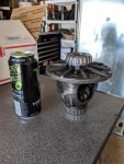
I'm using a rear diff from an 94' Mazda Miata that I will build my independent rear suspension. As you can see in comparison to a Monster can, it's quite compact and will be easy to mount in some pillow block bearings.
If I was doing a more hot rod style go kart I'd go your way, looks awesome!
If I was doing a more hot rod style go kart I'd go your way, looks awesome!
Attachments
-
 Diff.jpg93.1 KB · Views: 10
Kartorbust
Inmate #627
I'm interested in how you'll make the differential work on a chain and sprocket setup.
5814SpeedCo
Member
I'm interested in how you'll make the differential work on a chain and sprocket setup.
I'm going to have the raised surface on the differential milled down flat and then either have new holes drilled or get a sprocket blank and match the holes to the ones on the differential. Then I'll be able to bolt a chain sprocket to it. Then I'll be using the Miata axle stubs, axles, spindles, wheel hubs, wheels and brakes. This isn't going on a little kart, it will be for my family buggy build
Functional Artist
Well-known member
Allracing
Are ya gonna (or) do the axles need to be "spin" balanced, since ya cut & re-joined them?
I've had drive shafts shortened & they needed to be balanced
...or you could/would definitely feel it.
Are ya gonna (or) do the axles need to be "spin" balanced, since ya cut & re-joined them?
I've had drive shafts shortened & they needed to be balanced
...or you could/would definitely feel it.
J.S.@SMS
Road Hazard
I don't think that it's as big a problem on this. As long as he did a good job, it should be fine. That is unless he is going to make it pretty fast. I'd say that if you're going to be going faster than 40mph it might be something to think about.
PS: I have a $150 road bike (cheapest that I've seen) from walmart with wheels that are insanely out of balance (stupid wheel reflectors), but it's still stable at 31.3mph (I have a cheap speedometer).
PS: I have a $150 road bike (cheapest that I've seen) from walmart with wheels that are insanely out of balance (stupid wheel reflectors), but it's still stable at 31.3mph (I have a cheap speedometer).
Kartorbust
Inmate #627
Never heard of needing to balance a CV axle. I know driveshafts if modified need to be balanced out. Supposedly you're supposed to rebalance a driveshaft after replacing U-joints...smells like malarkey to me. Replaced many sets of driveshaft u-joints and never had any vibration problems.Allracing
Are ya gonna (or) do the axles need to be "spin" balanced, since ya cut & re-joined them?
I've had drive shafts shortened & they needed to be balanced
...or you could/would definitely feel it.
As long as the CV axles were shortened and welded or however it was put back together properly and not crooked, it should be fine.
ideally ALL rotating masses need to be balanced!
Anyways..
please take great care not to accidentally HiJack this thread.
'sid
Anyways..
please take great care not to accidentally HiJack this thread.
'sid
Good points on the balancing! I coudn’t see any evidence of the axles being balanced from the OEM. I believe that on fully machined parts they rely on the machining process being accurate enough for the part to be within balancing limits. The way I shortened the axles would comform to the same thinking - almost. When I cut them I had to use an angle grinder as they were very hard. The cut surfaces could have introduced som imbalance. Then I pressed the 2 pieces into a machined sleeve - no problem there. I had drilled the sleeve on each end for a plug weld so the final operation was to plug weld the axles to the sleeve. I did grind the plug welds flush to the sleeve, but of course some imbalance could have been introduced there. All in all I think I am going to be alright though, the axles rotate alot slower then the driveshaft. It might be another story when it comes to the driveshaft, we’ll see. I haven’t got the plan clear for that, other than that there will be a driveshaft 
I put in some work on the wheel spacers. There were two reasons for needing spacers: The bolt pattern nerden to be changed, and the wheels needed to be further out to clear the brake drums.
After having done some turning (Sorry no pics), the spacers went to the mill:


Presses in some of these:

And the wheels now mount:


Sent from my iPhone using Tapatalk
After having done some turning (Sorry no pics), the spacers went to the mill:
Presses in some of these:
And the wheels now mount:
Sent from my iPhone using Tapatalk
Bansil
Painter of gnomes....
As a machinist Myself ...
The pimped out "sine bar" on the press made me smile
Love the detail
The pimped out "sine bar" on the press made me smile
Love the detail
I believe I mentioned earlier that I had decided to try to build a sprung rear end. Doing so would require the frame to be "kicked up" and also to be a bit narrower than how I originally made it. My mind was firmly set on this idea, and hence I cut the frame to make the kick up:

With the steel still hot from cutting, I realised that the sprung idea was not going to work. the problem is the drive shaft which is going to run below the body/seat. When the cart sits nicely with a good stance, the drive shaft is very close to the underside of the body. Any suspension travel would mean rasing the rear end higher and would ruin the hot rod stance/look that I am after. I decided to go back to the original idea of a "hard tail". This was a relief as hanging the rear and making the drive shaft will be much easier. And I have the perfect frame for it too.........eeeeer had the perfect frame for it. Time to weld the frame back together

---------- Post added at 01:01 PM ---------- Previous post was at 12:59 PM ----------
Now I was able to focus on hanging the rear end. I started with some 10mm (slightly beefier than 3/8") flat bar and bored a hole corresponding to the axle tube diameter (51mm/2"):

Cut this piece in half to create tow saddles for the axle. Putting the axle on top of the frame gives the stance that I am after. By angling the pinion towards the ground I will be able to get the drive shaft under teh body, barely


The u-bolts are from some cheap exhaust clamps
With the steel still hot from cutting, I realised that the sprung idea was not going to work. the problem is the drive shaft which is going to run below the body/seat. When the cart sits nicely with a good stance, the drive shaft is very close to the underside of the body. Any suspension travel would mean rasing the rear end higher and would ruin the hot rod stance/look that I am after. I decided to go back to the original idea of a "hard tail". This was a relief as hanging the rear and making the drive shaft will be much easier. And I have the perfect frame for it too.........eeeeer had the perfect frame for it. Time to weld the frame back together
---------- Post added at 01:01 PM ---------- Previous post was at 12:59 PM ----------
Now I was able to focus on hanging the rear end. I started with some 10mm (slightly beefier than 3/8") flat bar and bored a hole corresponding to the axle tube diameter (51mm/2"):
Cut this piece in half to create tow saddles for the axle. Putting the axle on top of the frame gives the stance that I am after. By angling the pinion towards the ground I will be able to get the drive shaft under teh body, barely
The u-bolts are from some cheap exhaust clamps
Final work on hanging the rear end. Made these out of some 10mm (~3/8") aluminum:

Drilled them:


and hung the rear:


I'll weld the saddles to the axle at a later stage, for now i need to be able to fine adjust the pinion angle. Will also drill some holes in the frame and add some pins to the saddles for positive location of the rear end.
Next up probably making the brakes work
Drilled them:
and hung the rear:
I'll weld the saddles to the axle at a later stage, for now i need to be able to fine adjust the pinion angle. Will also drill some holes in the frame and add some pins to the saddles for positive location of the rear end.
Next up probably making the brakes work
- Status
- Not open for further replies.